Combining Several Fibers into One Fiber
The required output determines the architecture. Several wavelengths, two polarization components, or many spatial modes can share one fiber. Combining all power into one spatial mode, one polarization, and one spectral channel is a more restrictive problem.
Why reversing a splitter has a penalty
Reciprocity relates transmission between the same pair of optical modes in opposite directions. It does not say that unrelated inputs all couple with unity efficiency into one output mode.
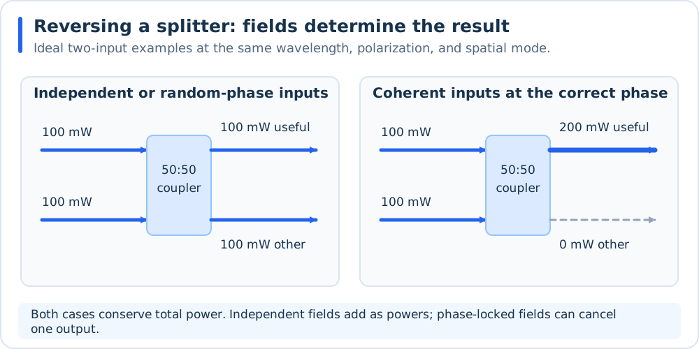
Equal input powers have different outcomes depending on their field relationship. These ideal two-input examples complement the general N-input calculation below; rejected power must still be accounted for.
For a symmetric splitter with forward common-port transmission \(\eta/N\) into each branch, the reverse transmission of each branch into that common port is also \(\eta/N\). Here \(\eta\) is the power transmission after excess loss. For mutually incoherent inputs, interference averages to zero, giving
Calculated example. Four independent 100 mW inputs into an ideal equal splitter used backward deliver 100 mW to the common port, rather than 400 mW. The other power occupies other device channels, radiates, or is dissipated, depending on the physical implementation.
This result is a scattering-model calculation for the specified optical modes. It does not apply to a wavelength router, a polarization combiner, or an output that accepts additional spatial modes. The general passive single-output constraint is \(\sum_j |S_{oj}|^2\leq 1\), with \(S_{oj}\) the field transmission from input \(j\) to output mode \(o\) at the frequency of interest. It prevents every independent input from having unit transmission into that same output mode.
There is also a practical packaging consequence: the unused arm of a 1-by-2 coupler can become an internally dumped output in reverse operation. Thorlabs discusses this explicitly in its PM coupler tutorial and manufacturer response. Use the manufacturer’s approved topology and account for rejected power.
Different wavelengths: WDM and spectral combining
A WDM routes wavelength bands, allowing each input wavelength to have high transmission to the common fiber. Implementations include fused wavelength-selective couplers, thin-film dichroic filters, and AWGs. For widely separated visible laser lines, a collimator/dichroic/fiber-launch assembly is another implementation.
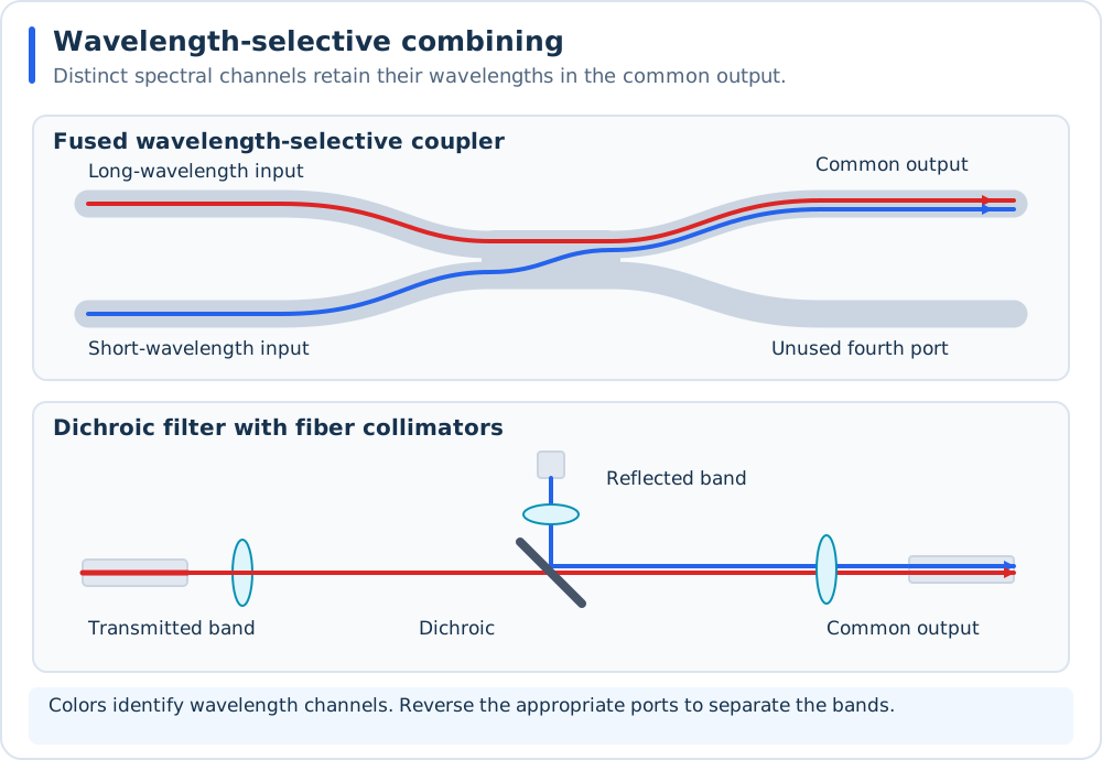
Fused and dichroic implementations route different wavelength bands into the common output. Red and blue identify spectral channels; the drawing does not assign particular wavelengths or passbands.
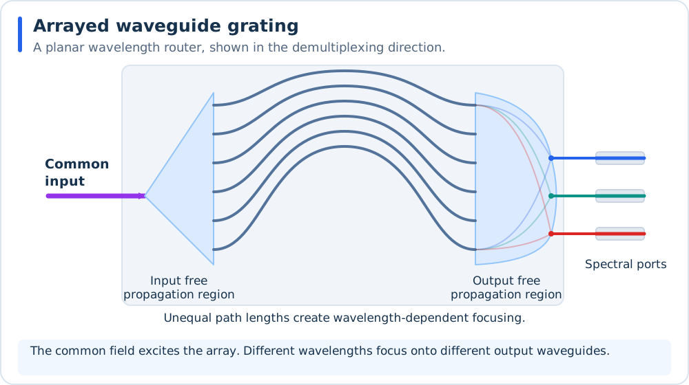
An AWG uses wavelength-dependent phase accumulation and focusing to route spectral channels. It is drawn as a demultiplexer; the corresponding ports support reverse multiplexing. See O4. Planar phased-array wavelength component, 1988 and R4. WDM/AWG routing: Smit and van Dam, 1996.
The output remains multiwavelength. It does not become a single optical frequency. Passband separation, linewidth, temperature drift, leakage between channels, and the common fiber’s guidance and attenuation across the entire spectrum determine suitability. An SM fiber at one wavelength may be multimode at a shorter wavelength.
Primary background includes O4. Planar phased-array wavelength component, 1988 and the R4. WDM/AWG routing: Smit and van Dam, 1996 review. A product example is Thorlabs’ two-wavelength PM WDM family.
High-power spectral beam combining can instead use free-space gratings or filters. A combined free-space beam still needs an adequately rated, well-matched fiber launch to satisfy a fiber-output requirement. The overall spectral/coherent distinction is developed in R1. Overall beam combining: Fan, 2005.
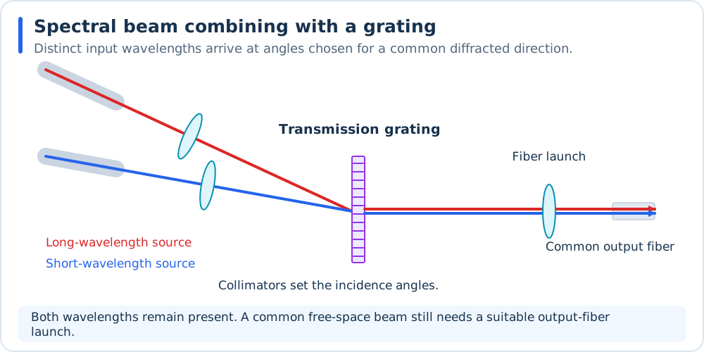
A grating can align distinct wavelengths onto a common output axis when the incident angles and diffraction order are chosen together. This schematic shows transmission geometry; reflective gratings offer another arrangement. The final fiber launch remains a separate design requirement. See R1. Overall beam combining: Fan, 2005.
Two polarizations: polarization beam combining
A PBC combines two suitably aligned, orthogonally polarized inputs into one spatial mode. Mutual phase locking is unnecessary for transferring their powers into the two orthogonal output polarization states. The result is not generally one fixed linear polarization.
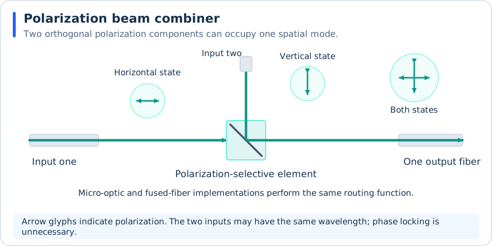
The polarization arrows describe optical states, not propagation directions. A micro-optic element is drawn; fused-fiber PBCs perform the same polarization-routing function. Reverse operation separates the two components.
There are only two independent polarization states per spatial mode. Repeated PBC stages alone therefore cannot combine an arbitrary number of independent same-wavelength sources into that same spatial mode without another distinction between channels. If a downstream linear polarizer selects one axis of two equal, mutually incoherent orthogonal components, it transmits only half their combined power in the ideal case.
Verify input polarization extinction ratio, axis/key conventions, insertion loss, and whether the common pigtail is SM or PM. Thorlabs’ fused-fiber PBC documentation describes bidirectional operation and the required axis alignment. PM fiber itself is not a polarizer.
Independent same-wavelength sources: multimode power combining
A tapered fused bundle merges several input fibers into an output with sufficient modal capacity. This can transfer a large fraction of the total input power while allowing a larger output core, a larger angular spread, or both. It does not promise the beam quality of a single diffraction-limited input.
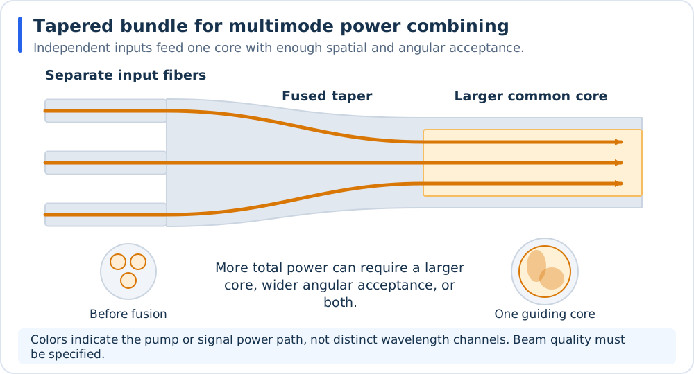
A power bundle provides enough output modal acceptance for independent inputs. Orange paths indicate power transport, not distinct wavelengths or three preserved output cores. See R2. Fiber power-combiner construction: Stachowiak, 2018.
Two practical classes must be distinguished:
Pump combiner: several pump fibers feed the inner cladding of a double-clad fiber. A pump/signal design adds a central signal path to the output core. Thus
(6+1)x1usually means six pump inputs and one signal input; check the vendor’s actual port definition.Signal power combiner: several laser outputs feed the guiding core of a common output fiber. Beam parameter product, mode content, and backward-power handling are central specifications.
The construction and difference between pump-only and pump/signal devices are reviewed by R2. Fiber power-combiner construction: Stachowiak, 2018. An original tapered-bundle disclosure is P5. Tapered bundles for cladding-pumped devices. For signal combining, Coherent’s kilowatt signal-combiner datasheet explicitly specifies output beam-quality parameters as well as power transfer. High transfer efficiency and single-mode output are separate requirements.
End-pump bundles interrupt and join the signal path. Taper-fused side-pump designs inject pump light along a signal fiber while retaining an uninterrupted signal core; see R6. Side-pump combiners: Lei et al., 2020. Pump injection followed by stimulated emission in a gain fiber is an active laser or amplifier process. It is not passive conversion of arbitrary pump beams into one coherent signal mode.
Lei’s full-text review also identifies input-pump NA sensitivity and fabrication-induced signal degradation. An uninterrupted core still needs suitable heating, fusion geometry, and control of mechanical deformation and dopant diffusion. Verify pump transfer, backward coupling, and signal beam quality together.
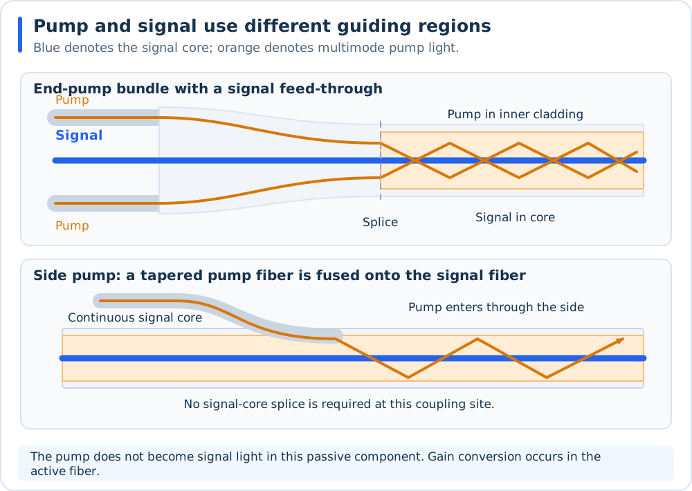
Pump and signal occupy different guiding regions in a double-clad output. End-pump bundles join fibers at a splice; side-pump structures retain the signal core through the coupling site. These conceptual layouts follow P5. Tapered bundles for cladding-pumped devices and R6. Side-pump combiners: Lei et al., 2020.
An initial acceptance-capacity calculation
For highly multimode, fully filled step-index fibers in comparable media, optical etendue scales as \(G\propto A\,NA^2\). A necessary capacity condition for transferring all independent input phase space is
Here \(A\) is guiding core area, or guiding inner-cladding area for a pump path. For \(N\) identical circular input cores of diameter \(d_{\rm in}\),
Calculated example. Seven fully filled 105 micrometre cores at NA = 0.22 require about a 278 micrometre output core at the same NA by this capacity estimate. A 200 micrometre output at NA = 0.22 has only
of the input acceptance. For equally bright, uniformly filled inputs, this implies at most about 52% throughput in that restricted model. Underfilled inputs can behave differently. Meeting the capacity condition is necessary, not sufficient: taper geometry, splices, bends, and leakage still determine real performance. This is an engineering screening calculation based on radiance conservation, not a component specification.
Photonic lanterns and spatial mode multiplexers
A photonic lantern adiabatically maps several SM cores into the modes of one few-mode or MM core. A sufficiently large output modal space allows independent inputs to remain independent optical degrees of freedom inside one fiber. For low loss in both directions over all supported modes, match the mode counts and maintain an adiabatic transition. Count polarization consistently on both sides.
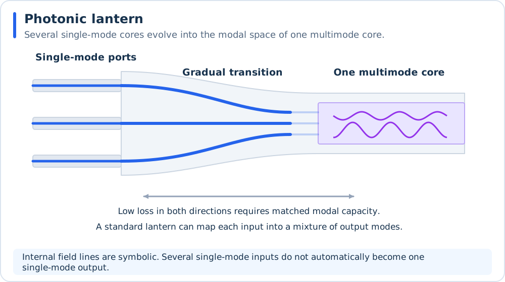
A lantern trades separate input cores for the spatial modal capacity of one output core. The field lines are symbolic; they do not imply that independent inputs all occupy its fundamental mode. See R3. Single-mode/multimode mapping: Birks et al., 2015.
An ordinary lantern does not guarantee a particular input-to-output-mode assignment. Mode-selective lanterns and other mode multiplexers address that mapping. Multi-plane light conversion (MPLC) implements spatial transformations with repeated phase manipulation and propagation; O7. Programmable spatial transformation, 2010 gives an experimental basis.
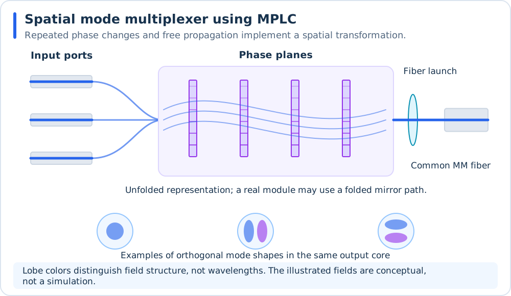
MPLC implements a designed spatial mapping. The optical path is unfolded for clarity; mode lobes and phase-plane shading are illustrative, with colors describing field structure rather than wavelength. See O7. Programmable spatial transformation, 2010.
The early lantern demonstration is O6. Early photonic-lantern demonstration, 2005; R3. Single-mode/multimode mapping: Birks et al., 2015 explains the wider technology. The 2005 proof-of-concept filter used 19 SM paths with a much larger MM mode count and measured only 3.4% off-notch transmission. Its principle and its measured efficiency must therefore be distinguished when tracing the development of low-loss lanterns.
A multicore-fiber fan-in is a further option if separate cores inside one physical fiber are acceptable. It does not merge their powers into one core.
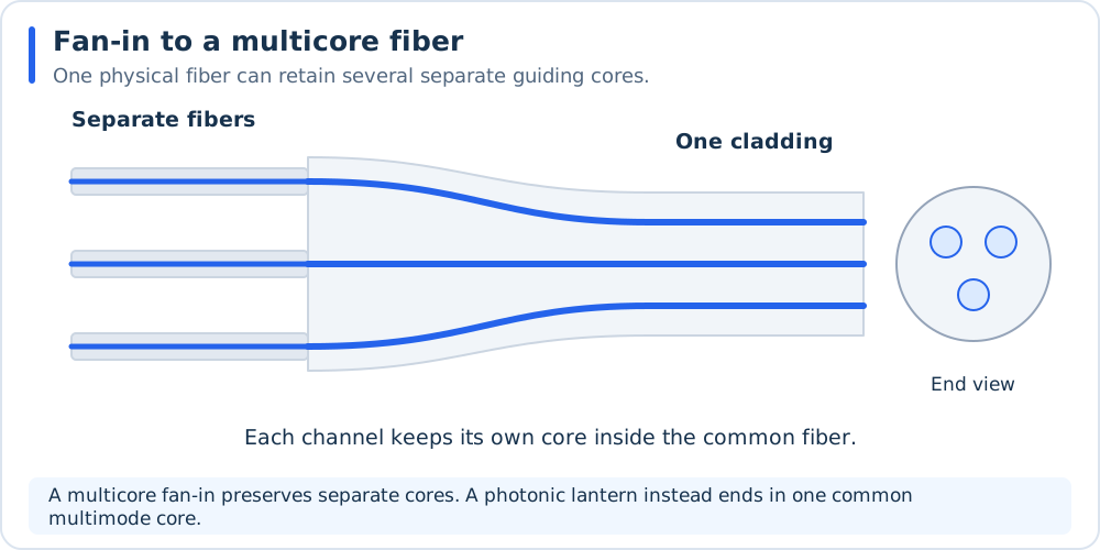
A multicore fan-in packages independent channels within one physical fiber while retaining separate cores. Its output is structurally different from the common multimode core of a lantern.
Same output mode and wavelength: coherent combining
Mutually coherent inputs can interfere constructively at one port and destructively at another. A useful ideal two-input model, with the coupler’s fixed phase included in the definition of \(\phi\), is
Here \(\gamma\) is normalized mutual coherence and field overlap, \(\phi\) is the residual relative phase, and \(\eta\) accounts for common transmission loss in this model. With equal powers, \(|\gamma|=1\), and \(\phi=0\), all transmitted power reaches the plus port. Random phase averaging instead reproduces the equal incoherent split between the two ports. For perfect overlap, \(P_+/(\eta(P_1+P_2))=\cos^2(\phi/2)\) when the powers are equal.
A practical system needs a shared coherent seed or another means of establishing mutual coherence, controlled polarization, field matching, and phase stabilization. Pulses also require temporal overlap and compatible dispersion. A fixed 50:50 coupler additionally requires equal input amplitudes to cancel the other output completely; a variable combiner can accommodate imbalance.
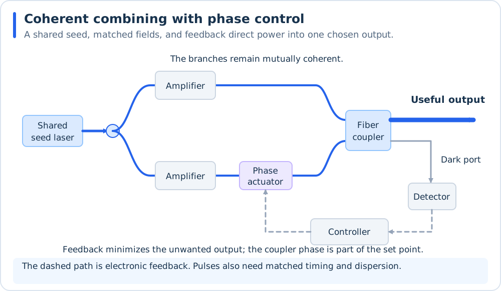
One practical coherent architecture controls relative phase using an unwanted-port measurement. Optical paths are blue and electronic feedback is dashed gray. The set point includes the coupler’s phase convention. See R1. Overall beam combining: Fan, 2005.
An early all-fiber experiment is O5. All-fiber laser beam combination, 1999: its cleaved active-fiber taper was a shared output mirror for two laser cavities, with injection locking obtained by tuning a Bragg grating. This supplies a concrete example of establishing coherence through coupled resonators. A later integrated all-fiber architecture is disclosed in P6. Integrated coherent fiber combining. For broad context, use R1. Overall beam combining: Fan, 2005.
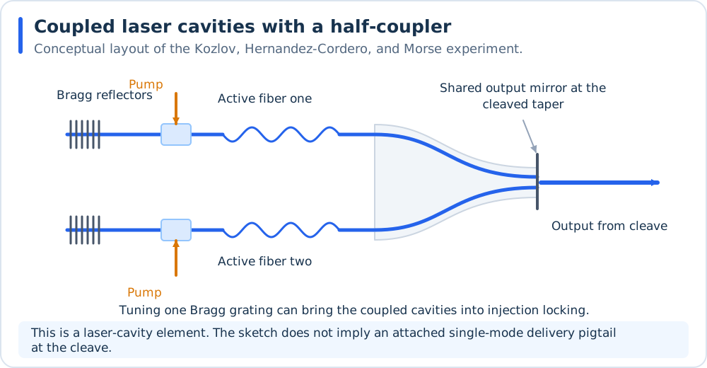
Original interpretation of the architecture in O5. All-fiber laser beam combination, 1999. The cleaved taper is part of both laser cavities. The sketch identifies the output at the cleave and does not add a delivery fiber that the drawing has not established.
At high power, the final fiber again concentrates power into a small guided region. Coherent combining does not remove output-fiber limits such as stimulated scattering, nonlinear phase, thermal effects, or facet loading. A free-space coherent-combining demonstration is therefore not automatically a demonstrated high-power single-fiber delivery system.
Time selection and switching
If only one source must use the output at any instant, a fiber switch can avoid the fixed split penalty for the selected path. Time interleaving can also place nonoverlapping pulse streams on a common output with a suitable switching arrangement. These are routing solutions; they do not sum simultaneous powers. Specify timing, extinction, switching speed, and output-fiber peak-power limits.
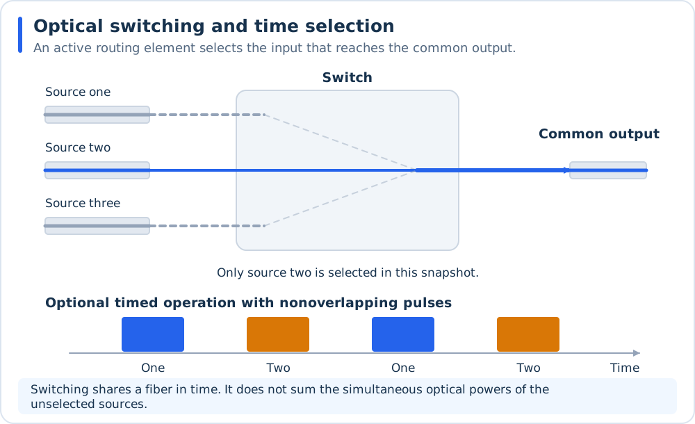
Selection and time interleaving share a fiber without adding simultaneous source powers. Dashed routes indicate unselected paths; the lower panel illustrates optional timed switching.