om05a Bench Geometry — Working Distance, A5 and the Motor Rail
The om05a inspection cell images two faces of one device down mirror-image arms. Light leaves a device face, is folded by the coaxial illumination prisms, crosses the big 50 mm right-angle prism, runs down a long air leg to the imaging lens, passes the filter, folds once more at RA mirror 2 and lands on the sensor.
Two gaps in that chain are not hardware — they are where the motors live. The
bench’s labels for them are A5 (in front of the lens) and C1 (behind it),
and the rule from the bench owner is that “A5 + C1 is where the motors can
travel; the C1 here is up to the Edmund Filter”.
This page shows the measured geometry of the 80 mm build
(attachment/om05a_folded_80mm.py), defines the working distance, and explains
the thing that surprises everybody: A5 = 0 does not mean the lens touches the
prism. The last section measures the other surprise — the bench’s stray light is
a single geometric leak between the two arms, and it is about a millimetre of
mirror edge.
Note
What is measured and what is modelled. The first three figures, the segment tables and the clearance numbers are measured from the scene file — rows, world body positions and one real traced ray — by:
taskset -c 0-9 nice -n 15 xvfb-run -a \
    .devenv/state/venv/bin/python -u docs/generate_om05a_bench_geometry.py
The stray-light figure and every number in that section come from a second, slower pass, which solves the worst case and traces it in its own process:
taskset -c 0-9 nice -n 15 xvfb-run -a \
    .devenv/state/venv/bin/python -u docs/generate_om05a_bench_geometry.py --ghost
The FOV / working-distance table and the travel chart come from the solver’s first order (its own conjugate solve), not from traced rays. Where a traced value exists and differs, both are given.
Chain coordinates are not physical distances
Every row thickness in the table below is a station coordinate in the row
model’s unfolded chain. Several bodies on this bench are placed absolutely by
desp (rows 1, 3, 5, 7 and 16), and the prism folds the beam through 90°
inside its own glass, so a row’s thickness and the distance the ray actually
flies are different quantities. The totals survive by cancellation; the splits do
not. Measured against one traced axial ray:
Segment |
chain (mm) |
traced (mm) |
note |
|---|---|---|---|
A1 |
5.35 |
8.55 |
device face → first RA mirror A |
A4 |
51.08 |
20.02 |
to the prism’s entrance face (44.73 to the fold point) |
A5 |
130.89 |
160.69 |
prism exit face → lens front datum |
C2 |
31.11 |
22.28 |
filter → RA mirror 2 |
arm |
45.98 |
55.18 |
RA mirror 2 → sensor (C2 + arm cancel: 77.09 either way) |
WD |
275.82 |
275.44 |
the 0.39 mm is row 9’s |
A5 is not a special case — it is simply the offset that matters, because it is the one a motor drives.
The chain, laid out straight
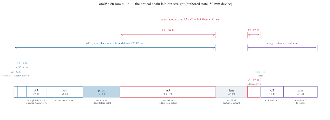
The row model laid out straight, at the authored 50 mm device. WD runs
from the device face to the lens front datum; the image distance runs from the
lens rear datum to the sensor. A5 and C1 are the two motor gaps, and
their sum, 148.40 mm, is the total motor travel.
Segment |
Rows |
mm |
What the row spans |
|---|---|---|---|
A1 (device-dependent) |
0 |
5.35 |
device face → first RA mirror A |
A2 |
1–2 |
11.50 |
→ BS cube A |
A3 |
3–4 |
27.00 |
BS cube A (row 3 reads 15.00; the ray crosses 13.50 mm of BK7) → centre RA mirror A |
A4 |
5–6 |
51.08 |
→ the 50 mm prism |
prism |
7 |
50.00 |
the folded glass path inside the right-angle prism (BK7) |
A5 (motor) |
8 |
130.89 |
prism exit → lens front datum |
WD (device-dependent) |
0–8 |
275.82 |
device face → lens front datum |
Only A1 moves with the device: the face travels half of any size change, so a 0.5 mm device puts A1 near 30.10 mm and WD near 300.57 mm. Everything else in that table is fixed hardware.
Segment |
Rows |
mm |
What the row spans |
|---|---|---|---|
lens block |
9–12 |
43.19 |
front datum → rear datum |
C1 (motor) |
13 |
17.51 |
lens rear datum → Filter 48-926 |
filter |
14 |
1.00 |
N-BK7 |
C2 |
15 |
31.11 |
→ RA mirror 2 |
arm |
16–24 |
45.98 |
RA mirror 2 → sensor |
image distance |
13–24 |
95.60 |
lens rear datum → sensor |
One FOV, one WD, one image distance
A field of view fixes the magnification, \(|m| = h_\text{sensor}/\text{FOV}\) with a 23.04 mm sensor, and a magnification fixes both conjugates. So each FOV has one working distance and one image distance, independent of device size.
The three FOVs below are the production bench’s operating points (20, 34×29
and 54×29, recorded in bugs/0767). They are listed here for reference; the
80 mm build’s own set is further down and is not the same. All values are
first order and datum-referenced — WD ends at the lens front datum and the
image distance starts at the rear datum, so they sit about 21.9 mm below the
thin-lens \(f(1+m)\) figure. The lens is a blackbox model (rows 10–12), and
\(f \approx 82.4\) mm is a fitted effective focal length, not a datasheet
value.
FOV (mm) |
|m| |
80 mm WD (mm) |
80 mm image (mm) |
production WD (mm) |
production image (mm) |
|---|---|---|---|---|---|
20 |
1.152 |
153.85 |
155.40 |
141.47 |
161.59 |
34 |
0.678 |
203.92 |
116.31 |
193.20 |
121.21 |
54 |
0.427 |
275.44 |
95.64 |
267.10 |
99.84 |
Warning
FOV 20 on the 80 mm build. Until bugs/0784 the lens could not reach it
below a ~32 mm device — a row limit, not a hardware one. The bodies allow it
(a 0.5 mm device needs 146.7 mm against 155.8 mm of clearance), so it is now
reachable; what remains true is the field: the one traced FOV-20 case on this
scene, a 50 mm device, captures only 0.40 of it. The production columns are
first order only: bugs/0783 records that production’s traced image does not
yet form where its first order says.
The 80 mm WD of 275.44 mm at FOV 54 is the first-order figure; the segment
table’s 275.82 mm is the row sum at the authored state. The difference is
row 9’s desp_z.
When the device size changes, only the device face moves — by half the size
change on this split-field bench. The working distance is restored by moving the
whole imaging group (lens, filter, RA mirror 2, camera) by that same amount, and
the image distance does not change. bugs/0783 does exactly that in one move,
when the scene has a MOTOR 1 group stage, the image distance already sits at
the requested FOV’s operating point, a measured traced focus agrees, and the
request is not forced; otherwise the full solve runs.
The folded reality
The chain above is unfolded. The real bench folds twice, into two orthogonal planes: the object arm lives in the y–z plane at \(x \approx 0\), and the imaging leg in the x–y plane at \(z \approx -25\).
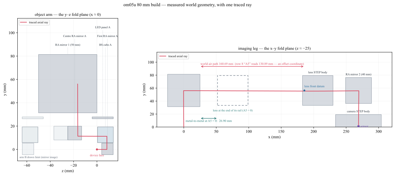
Measured world geometry with one real traced ray, and the lens drawn a second time (dashed) where the end of its rail would put it. The prism’s exit face is at \(x = 25.000\); the lens front datum at \(x = 185.689\). The ray flies 160.69 mm of air between them — while row 8, “A5”, reads 130.89 mm.
Why A5 is not the air gap
A5 is an offset coordinate, not a physical distance. The traced ray measures 160.69 mm of air where the row reads 130.89 mm. The 29.80 mm difference has an exact, measured decomposition:
30.187 mm — row 8’s station origin sits that far past the prism’s exit face along the leg. Most of it is the prism’s own folded glass path: the ray enters the prism’s lower face, crosses 24.71 mm of glass to the hypotenuse, turns, and crosses another 25.29 mm along \(+x\) to the exit face (24.71 + 25.29 = 50.000, exactly row 7). Row 8’s zero therefore starts well past the fold point, over a span the beam spends inside glass.
0.389 mm — row 9’s
desp_zseat offset, which is why row 8 overshoots the lens datum by that much.
The prism’s optical exit surface is its metal face: its analytic face centroid, its true mesh extreme and the traced ray’s exit vertex all land on \(x = 25.000\). There is no body setback.
So what does A5 = 0 mean?
Driving the lens to \(A5 = 0.001\) moves the barrel exactly 1:1 with the row gap — from \(x = 182.79\) to \(x = 51.90\) — while the prism face stays at \(x = 25.000\):
authored (mm) |
at A5 ≈ 0 (mm) |
|
|---|---|---|
lens front datum |
185.69 |
54.80 |
lens barrel front face |
182.79 |
51.90 |
prism exit face |
25.00 |
25.00 |
metal-to-metal |
157.79 |
26.90 |
At the end of its rail the lens still has 26.90 mm of clearance to the bare prism wedge — 24.90 mm after the mover’s own 2 mm mechanical allowance.
bugs/0771 quotes a different figure, 19.85 mm: that is a 3D minimum distance
to the whole prism assembly (which carries parts nearer than the bare wedge),
and it was measured at \(A5 = 0.889\), not at the rail end. Its own model,
body_gap = A5 + 18.96, puts the assembly figure near 18.96 mm at
\(A5 = 0\). Both are positive and both exceed any shortfall discussed below.
The consequence: at the small-FOV end the lens used to be stopped by the row/station partition — the motor rail as drawn — not by a collision. Since bugs/0784 the mover recovers that headroom, so the stop is the metal.
Why a smaller FOV cannot be reached
A smaller FOV is a higher magnification, and a higher magnification needs the lens closer to the device:
so with the fitted \(f \approx 82.4\) mm and \(h_\text{sensor} = 23.04\) mm, the object distance is linear in the FOV: every 1 mm of FOV costs 3.576 mm of lens travel toward the object. The row gap A5 holds 130.89 mm of that. The row is not the limit: bugs/0784 recovers a shortfall from the nearest upstream air gap, so the lens runs until its body reaches RA mirror 1 at 155.79 mm.
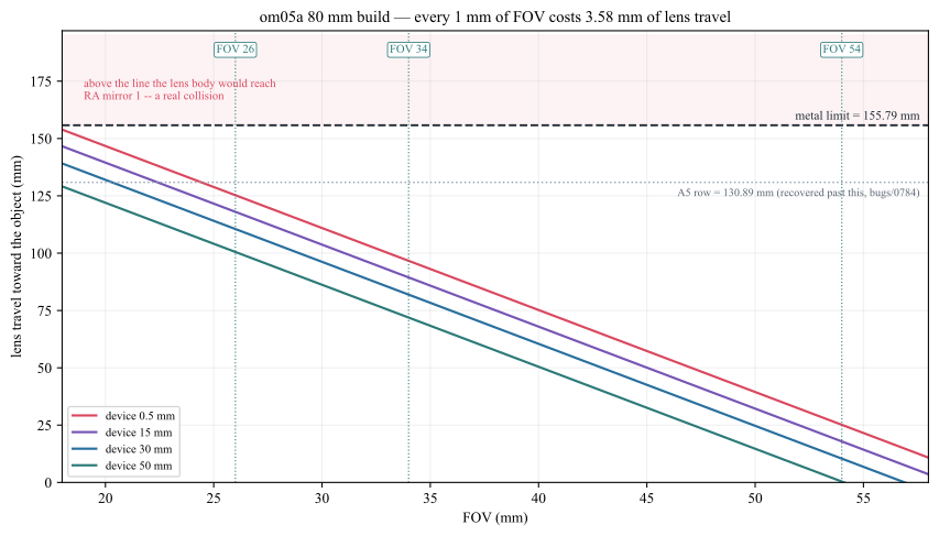
First order, not traced. Above the dashed line the lens body would reach RA mirror 1 — a real collision. The dotted line is the A5 row gap, which is bookkeeping: bugs/0784 recovers a shortfall against it from the nearest upstream air gap. A smaller device pushes its face further from the lens and so demands more travel — which is why the small-FOV limit is set by the smallest device.
FOV |
need @ L = 0.5 |
A5 left |
need @ L = 24 |
A5 left |
|---|---|---|---|---|
20 |
146.72 |
−15.83 |
134.97 |
−4.08 |
22 |
139.56 |
−8.67 |
127.81 |
+3.08 |
24 |
132.41 |
−1.52 |
120.66 |
+10.23 |
26 |
125.26 |
+5.63 |
113.51 |
+17.38 |
A negative entry in that table is where the row runs out, not the machine. bugs/0784 recovers exactly that shortfall — it shifts the missing millimetres out of the nearest upstream air gap into the lens gap and compensates every body in between, so nothing moves and the conjugate is unchanged. What remains is the metal:
For a 0.5 mm device that moves the floor from FOV 24.4 to about 17.5. Traced on the shipped scene: 0.5 mm at FOV 23 lands at 2.28 µm with 19.8 mm of clearance left, 20 mm at FOV 21 lands at 2.48 µm, and 0.5 mm at FOV 17 is still refused — it needs 157.4 mm where 155.8 mm of body clearance exists.
The 80 mm operating points
FOV (mm) |
devices (mm) |
A5 at L = 0.5 (mm) |
lens → RA mirror 2 (mm) |
traced spot on the sensor |
|---|---|---|---|---|
26 |
0.5–24.8 |
+5.63 |
55.2 |
1.90–1.94 µm (traced to L = 24) |
34 |
0.5–32.4 |
+34.24 |
38.0 |
1.31–1.35 µm (traced to L = 30) |
54 |
0.5–51.4 |
+105.76 |
17.4 |
0.65–1.95 µm (traced to L = 50) |
Every traced case lands well inside one 4.5 µm pixel, at full capture, with
positive clearances and both motor stages inside their rails. The FOV 26 floor was
set by the row gap running out; since bugs/0784 recovers that headroom the
floor is the metal, and lower settings are reachable — a 0.5 mm device at FOV 23
traces 2.28 µm with 19.8 mm of clearance. Three caveats a reader should carry:
The device ranges come from a 5 % field margin and run past the traced cases (24, 30 and 50 mm). The extra 0.8 / 2.4 / 1.4 mm is first-order extrapolation. At FOV 34 full capture is known to break somewhere above 30 mm — a 50 mm device there captures only 0.68.
The FOV-54 band’s 1.95 µm upper end is the authored 50 mm case, where the solve found the field already delivered and moved nothing; it traced 106 rays against 314–962 for the other FOV-54 cases, whose spots are 0.65–0.68 µm.
“Lands” is not “clean”. At FOV 26 a 0.5 mm device still carries 36 cross-arm ghost rays reaching the sensor up to 2.96 mm outside the image — measured in Stray light — the two arms can see each other below. Since
bugs/0784lifted the mechanical floor to about FOV 17.5, that section is what now argues for stopping at 26: going to 23 costs no clearance but nearly doubles the stray light. The floor is a stray-light choice, not a rail limit.
Stray light — the two arms can see each other
Every traced case above lands inside a pixel, but “lands” is not “clean”. A small share of the light that leaves a device face reaches the sensor by a different route. On this bench that route is not scatter and not a coating artefact: it is a geometric leak past the edge of one mirror.
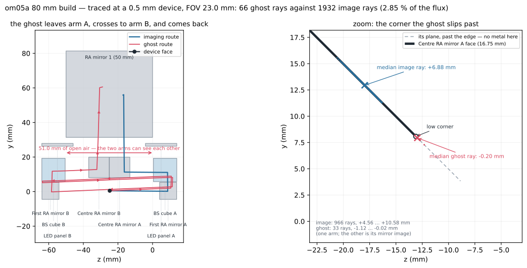
Traced at the worst corner the bench can be asked for — the smallest device at the lowest FOV that still solves. Left: the imaging route and the ghost route in the object arm’s fold plane. Right: where each one crosses centre RA mirror A’s face. The image ray lands on the mirror; the ghost crosses just past its low corner and keeps going.
Where it comes from
Light off face A reflects at first RA mirror A, turns down inside BS cube A and runs back along \(-z\) toward centre RA mirror A, which folds it into the 50 mm prism. That mirror’s optical face is 16.75 mm across (a 45° flat, so the diagonal of an 11.84 mm AABB). A ray that crosses the face plane below its low corner misses the mirror altogether and carries straight on — and the next thing on that line, 51.0 mm further along \(-z\), is arm B’s BS cube.
Traced at a 0.5 mm device and FOV 23, counting each crossing along the face from its low-\(y\) corner (per arm; the other arm is the mirror image, ray for ray):
route |
rays |
crosses at |
what happens |
|---|---|---|---|
imaging route |
966 |
+4.56 … +10.58 mm (median +6.88) |
onto the face — it reflects into the prism |
ghost route |
33 |
−0.02 … −1.12 mm (median −0.20) |
past the low corner — it flies on to arm B |
Two things in that table are worth reading twice. The imaging bundle keeps 4.56 mm of margin to the corner — it is not grazing anything, and rays that cross between 0 and 4.56 mm do strike the mirror but are then stopped at the aperture stop, so they never land. And the ghosts are a narrow band, 1.1 mm wide, immediately past the corner: miss by more than that and the ray never finds its way back to the sensor at all. The leak is about one millimetre of mirror edge, not a coating and not a scattering model.
The route, hit by hit
After it misses, the ghost enters BS cube B through the near face at its very
bottom edge, totally internally reflects off the cube’s bottom face, reflects off
cube B’s cement diagonal, leaves through the bottom face and reflects off first RA
mirror B. From there it runs the length of the bench back into arm A, hits
first RA mirror A and re-enters the ordinary imaging path — cube A a second time,
the centre mirror, the prism, the lens, the filter, RA mirror 2, the sensor. Its
surface_ids route is 26 hits long against the imaging route’s 17:
imaging   1  3 3 3   5            7 7 7   9 10 11 12 13 14 15 16   25
ghost     1  3 3 3   18 18 18 18  17  1  3 3 3  5  7 7 7  9 … 16   25
Arm B produces the mirror image of it, ray for ray and millimetre for millimetre: its ghosts leave through centre RA mirror B’s corner, visit cube A, and land the same 8.21 mm from their own field.
One hit in that chain looks suspicious and is worth checking, because a bounce inside a cube is exactly what a wrong model produces:
measured |
meaning |
|---|---|
|
the engine’s own label for total internal reflection |
turn 4.49° |
a reflection turns the ray by \(180^\circ - 2\theta_i\), so \(\theta_i = 87.8^\circ\) |
\(n = 1.5185\) (BK7) |
critical angle \(\arcsin(1/n) = 41.2^\circ\) |
At 87.8° the ray is 46° past the critical angle: this is real total internal reflection at grazing incidence, not a modelling artefact. Nothing in the ghost route needs a coating to exist.
The cement diagonals are modelled as 100 % mirrors
The one place the model is optimistic: each BS cube’s cement diagonal is
authored function: "Mirror" and reflects 100 %, even though the row stores
split_ratio: 0.5. The engine reads split_ratio only when the face’s
function is "Beam Splitter".
The ghost route takes three cement reflections where the imaging route takes one, so a real 50/50 coating would divide the ghost-to-image ratio by \(0.5^2 = 4\). Every measured share below is therefore an upper bound, and the column beside it is the same number with that correction applied.
Simply re-marking those faces "Beam Splitter" is not the fix — tried on a
probe copy of the scene, it collapses the trace (460 paths, none landing: 410
vignette at the stop, 50 with no next intersection), while a control copy with the
same rows re-serialised and no value changed traces identically to the shipped
scene. Branching those faces disturbs the launch and pupil aim; that is its own
piece of work, not a scene edit.
What it costs the picture
device |
FOV |
image rays |
ghosts |
ghost flux |
with 50/50 cement |
landing on the picture |
|---|---|---|---|---|---|---|
17 mm |
21 |
644 |
6 |
0.78 % |
≈ 0.20 % |
none (≤ 1.70 mm outside) |
0.5 mm |
26 |
1932 |
36 |
1.57 % |
≈ 0.39 % |
none (≤ 2.96 mm outside) |
0.5 mm |
23 |
1932 |
66 |
2.85 % |
≈ 0.71 % |
none (≤ 6.07 mm outside) |
Flux here is the sum of each landing ray’s branch_power — 0.771 for an image
ray, 0.59–0.71 for a ghost — not a ray count.
So the answer to “how much does the stray light reduce image quality?” is, on these settings, nothing measurable. Every ghost ray lands outside the two field strips, 2.3–24.7 mm from where its own field point images. The measured image RMS stays at 2.28 µm at 0.5 mm / FOV 23, against a 4.5 µm pixel — the ghosts are not in it because they are not on it. What is affected is a reading of the whole sensor frame: there the ghosts appear as a faint patch a few millimetres off the picture, carrying up to ~0.7 % of the image flux once the cement coatings are right.
The caveat is the sampling. These are traced pupil samples, not a radiometric stray-light budget: they prove the route exists, where it lands and roughly how strong it is, but a real veiling-glare figure needs the coating data and a much denser launch.
Smaller FOV, more stray light
The trend in that table is real and it is the one the bench owner expects: a smaller FOV is a larger magnification, a shorter working distance and a lens carried further forward, and it makes more stray light. At a fixed 0.5 mm device, FOV 26 → 23 nearly doubles the ghost count (36 → 66) and the flux share (1.57 % → 2.85 %).
But it is not the cone growing. The working distance only shortens from 175.3 mm to 164.6 mm over that step, so the accepted cone widens by 6.5 % — which cannot double anything, and in any case the imaging bundle keeps 4.56 mm of margin to the corner at both settings. What changes is the other end of the route: a ghost has to come back through the same aperture stop as the image, and moving the lens forward changes which of the missed rays do. The measurement is solid; the sensitivity is worth its own run before anyone leans on it.
The device size moves it the same way, and harder: at FOV 26 a 17 mm device produces no ghosts at all, while a 0.5 mm device — whose face sits further from the lens, so MOTOR 1 carries the imaging group closer to the prism — produces 36. FOV 34 at 17 mm is also clean.
The lesson for the bench is that this is cheap to fix in hardware. The ghosts all cross within 1.12 mm past the mirror’s low corner, and the imaging bundle stays 4.56 mm clear of it, so an opaque lip about 1.2 mm long, in the mirror’s own plane, past its low corner intercepts the whole measured band without touching the image. Nothing in the optics has to change. That is a bench change for its owner to make: the app never moves, slides or hides vendor hardware on its own — only the device under test changes size, and the motors follow it.
What the app reports
bugs/0779 and bugs/0780 keep these rays out of the focus measurement (1 %
of rays on another route once turned a 2 µm spot into 656 µm) and draw them faint.
The banner’s share, however, counts rays on any other route — ghosts plus the
bookkeeping strays that merely skipped the stop — and does not weight them by
power. At 17 mm / FOV 21 it reads 10 of 654 rays, 1.53 %, where the six ghosts
carry 0.78 % of the image flux. Display already weights by branch_power
(bugs/0604); the stray-light and focus measurements do not. Read the banner as
“how many rays”, and this page’s table as “how much light”.
Notes for maintainers
Figures 1–3 are regenerated by
docs/generate_om05a_bench_geometry.py; it re-measures the scene and re-traces, so a scene change is reflected by re-running it, never by editing the SVGs.A5isrows[front - 1].thicknessandC1isrows[rear].thickness, withfront, rear = editor._imaging_lens_block_indices()— rows 8 and 13 on this scene, whose lens block is rows 9–13.The motor model is
bugs/0759(two motors),bugs/0782(MOTOR 1 moves the group along the beam on any frame — its seat sign is measured, because the production build’s lens leg runs the other way) andbugs/0783(a device change restores the WD in one move).bugs/0784recovers lens-gap headroom from the nearest upstream air gap when the row is short and the bodies are not, which is why the row floor above is a waypoint rather than a limit.The stray-light section is measured by the same script’s
--ghostpass, which solves the 0.5 mm / FOV 23 corner and traces it; it writesmeasured_ghost.jsonbeside the SVGs, so every share, count and crossing on this page can be checked against the run that produced it. Run it in its own process — it starts a second app. Two things in that pass are deliberate and easy to break: which diagonal of a 45° mirror’s AABB is its optical face is decided from the traced hits, not assumed; and the crossing test is anchored on the BS cube’s exit face rather than on a sign change, because an imaging ray lands exactly on the mirror plane and its signed distance there is ±1e-16 — a sign test finds it for half the rays and silently skips the rest.The stray-route classification is
bugs/0779(keep another route out of the focus measurement) andbugs/0780(draw it faint). Neither weights bybranch_power; the shares in the table above do.Guards:
python -m KrakenOS.UI.validate_open3d_0782_motor1_follows_the_beam,python -m KrakenOS.UI.validate_open3d_0783_device_change_restores_wdandpython -m KrakenOS.UI.validate_open3d_0784_lens_leg_headroom_is_the_metal.