Fiber Splitters and Combiners: Technology Survey
Research date: 19 October 2026. This survey addresses both a single fiber feeding several fibers and several fibers feeding one fiber. It covers power distribution, wavelength and polarization routing, multimode power combining, and coherent laser combining. No wavelength, power level, fiber type, or channel count has been specified, so the recommendations identify suitable architectures rather than a particular purchase.
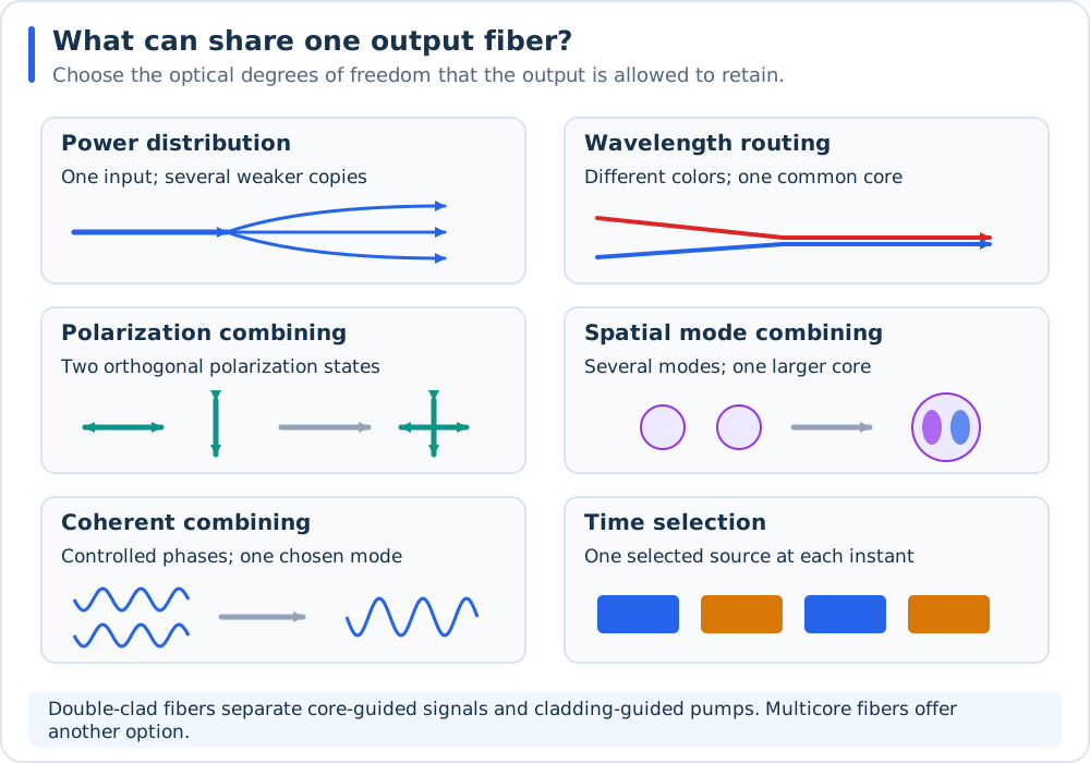
The allowed output determines the architecture. One physical fiber can carry several wavelengths, polarization states, spatial modes, or cores.
All illustrations in this survey are original conceptual SVG schematics. They show operating principles and optical paths; dimensions, field patterns, and component shapes are illustrative. Each figure defines its colors, and numerical power examples assume ideal components.
The practical starting points are:
Distribute the same optical spectrum: use a fused-fiber coupler for a small number of branches or a planar lightwave circuit (PLC) splitter for a larger fan-out. Each branch receives a fraction of the power.
Combine different wavelengths: use a wavelength-division multiplexer (WDM), or a fiber-coupled dichroic assembly for suitable laser lines.
Combine two orthogonal polarizations: use a polarization beam combiner (PBC). Both polarization components remain in the output.
Combine independent sources at the same wavelength: use a larger multimode output when its beam quality is acceptable. Preserving one spatial mode and one polarization with high efficiency requires mutual coherence and control of the fields.
These distinctions follow the beam-combining framework reviewed by Fan (2005) and the guided-mode mapping described by Birks et al. (2015).
Important
One output fiber does not necessarily mean one spatial mode, one polarization, or one wavelength. Reversing a reciprocal splitter also does not automatically deliver the sum of independent input powers into its common port. See Combining Several Fibers into One Fiber for the power accounting.
Technology map
Technology |
One fiber to several fibers |
Several fibers to one fiber |
Main constraint |
|---|---|---|---|
Fused biconical taper (FBT) coupler; fused star coupler |
Divides power between branches; fixed or unequal ratios |
Mixes fields, with a coupling-ratio penalty for independent inputs |
Wavelength, polarization, and modal dependence |
PLC splitter; integrated Y-branch or multimode-interference circuit |
Compact distribution to many fiber pigtails |
Reverse common-port transmission retains the splitting penalty |
Fiber coupling, bandwidth, and package power rating |
WDM: fused, thin-film filter, arrayed waveguide grating (AWG) |
Separates spectral channels |
Routes distinct wavelength bands into a common fiber |
Passbands, isolation, drift, and fiber guidance at every wavelength |
Polarization beam splitter / combiner |
Separates orthogonal polarization components |
Combines two orthogonal components in one spatial mode |
Two polarization dimensions per spatial mode |
Tapered fused bundle; multimode signal combiner |
Reverse distribution is device- and launch-dependent |
Adds power into a larger modal acceptance |
Output core, numerical aperture, and beam quality |
Pump/signal combiner |
Specialized core/cladding routing |
Preserves a signal path while injecting pump power into cladding |
Pump and signal occupy different guiding regions |
Photonic lantern; spatial mode multiplexer |
Maps multimode light into several single-mode ports |
Maps separate inputs into modes of one few-/multimode core |
Sufficient output modes; adiabaticity or mode-conversion accuracy |
Coherent combiner |
A splitter can supply coherent seed branches |
Adds mutually coherent fields into a selected output mode |
Phase, polarization, amplitude, and temporal overlap |
Optical switch |
Selects one branch at a time |
Selects one input at a time |
Does not add simultaneous input powers |
The table is an engineering synthesis. Mechanisms, sources, calculations, and qualifications are developed in the following pages.
Where to start reading
For a broad historical catalog of fiber splitters and coupler constructions, start with R7. Historical fiber-coupler overview: Agarwal, 1987. For an overall view of beam combining, start with R1. Overall beam combining: Fan, 2005. For physical fiber-combiner construction, read R2. Fiber power-combiner construction: Stachowiak, 2018. For why several single-mode fibers can feed one multimode fiber efficiently, read R3. Single-mode/multimode mapping: Birks et al., 2015. For the separate fiber-to-chip interfaces of an integrated solution, read R8. Fiber-to-chip interfaces: Marchetti et al., 2019. The Reviews and Original Research page also covers PLC and AWG reviews and selected original demonstrations. The Patent Reading Guide page provides named inventors, dates, and technical disclosures.
The Full-Text Access and Download Requests page explicitly identifies papers whose full texts could not be obtained, and distinguishes a downloaded manuscript from an abstract-only assessment.