Splitting One Fiber into Several Fibers
First decide whether every branch needs the same spectrum, or whether different branches should receive different wavelengths, polarizations, or spatial modes. Only the first case is ordinary power splitting.
For a broad historical review of fiber-coupler constructions, see R7. Historical fiber-coupler overview: Agarwal, 1987. Its diagrams and discussion complement the selected architectures below; its quoted performance is not a modern component specification.
Fused-fiber power splitters
An FBT coupler is made by heating and stretching adjacent fibers into a coupled taper. A 2-by-2 device exposes both ports at each end. A packaged 1-by-2 device may terminate one port internally. Coupling length and geometry determine the split ratio; cascades or multi-fiber structures provide more outputs.
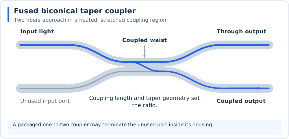
An FBT coupler exchanges guided optical power in a shared waist. The blue paths indicate power transfer, rather than individual rays or a calculated field distribution.
This is a useful starting point for a two-way split, a monitoring tap, or a small distribution tree. Choose single-mode (SM), polarization-maintaining (PM), or multimode (MM) fiber to match the source. PM fiber preserves properly launched polarization; it does not turn unpolarized light into one linear polarization.
Early primary sources are Kawasaki and Hill (1977) for MM access couplers and Kawasaki, Hill, and Lamont (1981) for SM fused biconical tapers. Both full papers were checked. Their reported excess losses concern specific experimental devices and launch conditions, rather than a universal specification for modern splitters; see the detailed notes in Reviews and Original Research.
For current component examples, Thorlabs documents 1550 nm 2-by-2 fused couplers and 1550 nm PM 1-by-2 couplers. These examples establish available device categories, not suitability for an unspecified laser. Check the exact fiber, operating band, split-ratio tolerance, and termination-dependent power rating.
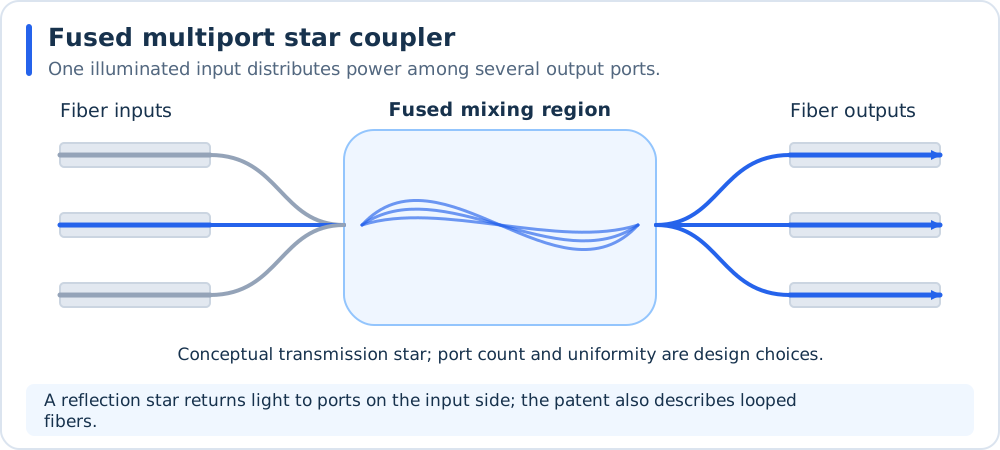
A conceptual transmission star distributes an input among several output ports. Reflection and hybrid stars use different port layouts; Patent Reading Guide describes the looped-fiber implementation in P2.
PLC and other integrated splitters
A PLC uses planar waveguides, often silica on silicon, with branching structures to distribute light to fiber arrays. Cascaded Y-junctions are one implementation; integrated directional couplers and multimode interference (MMI) structures provide other splitting mechanisms. Here “multimode interference” describes the internal waveguide region; the external pigtails can still be single-mode.
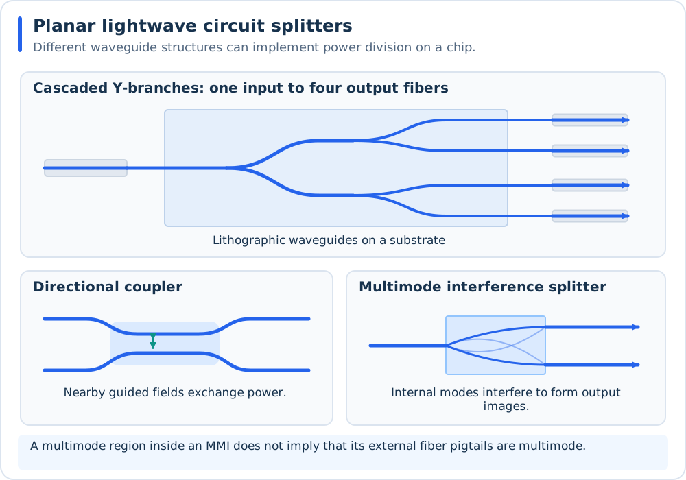
Y-branches divide the path geometrically, directional couplers exchange power between neighboring guides, and MMI devices use internal modal interference. The same tree topology can also be built from discrete fused couplers. See R5. Planar-circuit background: Singh, 1999 for planar-circuit context.
PLC packaging is attractive when many outputs must fit into one module. Do not assume that a telecom splitter is suitable for visible light, ultrashort pulses, or high-power fiber lasers. Material transparency, waveguide modes, fiber coupling, dispersion, and thermal behavior all need to match the application.
For silicon photonic implementations, R8. Fiber-to-chip interfaces: Marchetti et al., 2019 reviews the fiber-to-chip interfaces. That coupling operation is separate from the on-chip splitting function; a silicon photonics interface design is not automatically applicable to a silica PLC package.
An early experimental reference is Hibino et al. (1994): its publisher abstract describes fiber-connected 1-by-8 and 1-by-32 silica PLC modules and reliability evaluation. For background, see R5. Planar-circuit background: Singh, 1999. An industrial example is Corning’s PLC splitter family.
Packaged free-space splitting
Another arrangement collimates the input fiber, divides the beam with beamsplitters or a diffractive optical element, and focuses each branch into an output fiber. It can accommodate unusual wavelengths or ratios, but each fiber launch adds an alignment and mode-matching problem. Its engineering trade-off is optical flexibility against alignment, packaging, coating, and coupling losses. See Active Fiber Alignment: Power, Dither, and Spatial Sensing for the overlap calculation.
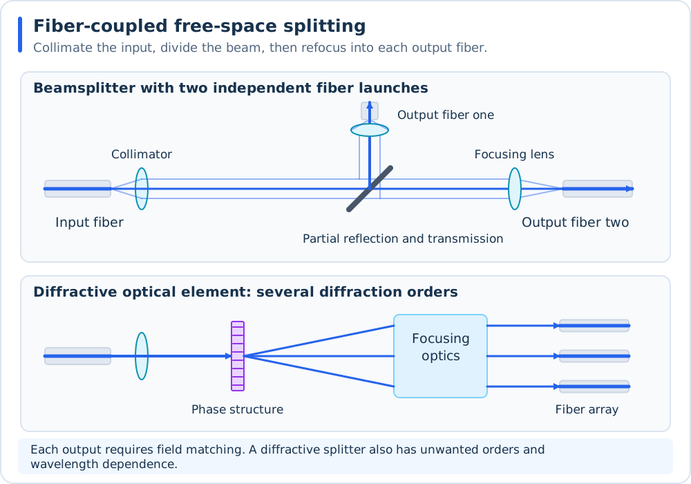
Free-space splitting requires a separate fiber launch for each output. A beamsplitter divides reflection and transmission; a diffractive optical element creates several orders that are relayed into a fiber array. Optical paths are schematic, not a ray-traced prescription.
For a coherent laser, splitting also establishes relative branch phases. Separate branch lengths then introduce phase drift and pulse delays. Equal powers alone do not guarantee equal arrival times or stable interference downstream.
Splitting by wavelength, polarization, or mode
WDM demultiplexer: each output receives a selected spectral band. The reverse direction is wavelength combining. The AWG approach is reviewed in R4. WDM/AWG routing: Smit and van Dam, 1996.
Polarization splitter: two outputs receive orthogonal polarization components. Their power ratio depends on the input polarization. A fused-fiber polarization splitter is a concrete implementation.
Photonic lantern or mode demultiplexer: several SM ports receive a mapping of a multimode input field. This does not inherently give equal powers or identical fields in every port. See R3. Single-mode/multimode mapping: Birks et al., 2015 and O7. Programmable spatial transformation, 2010.
The wavelength-routing, polarization, and photonic-lantern diagrams on the combining page also illustrate the corresponding splitting functions when the specified ports and modes are used in reverse.
Power and loss accounting
For an ideal equal splitter with \(N\) outputs, each branch receives \(P_{\rm in}/N\). Define branch insertion loss and splitter excess loss separately:
Here all powers are measured at explicitly defined reference planes. For equal branches, \(IL_j=10\log_{10}N+EL\). Unequal devices require their actual branch transmissions. Manufacturer specifications may include or exclude connectors; retain the same convention throughout the budget. Thorlabs’ coupler documentation also distinguishes insertion loss from excess loss.
Number of outputs |
Power in each branch |
Ideal branch loss |
|---|---|---|
2 |
50% |
3.01 dB |
4 |
25% |
6.02 dB |
8 |
12.5% |
9.03 dB |
16 |
6.25% |
12.04 dB |
32 |
3.125% |
15.05 dB |
64 |
1.5625% |
18.06 dB |
Calculated example. A 100 mW input, eight equal outputs, and 0.6 dB excess loss give
The total output is 87.10 mW. The 9.03 dB ideal division is redistribution of useful power, not 9.03 dB of absorption inside the package. For a cascaded tree, add the branch insertion losses along each actual path; do not add the ideal split penalty a second time.
Multimode launch sensitivity
An MM splitter’s ratio can change when the input mode distribution changes. Core size and nominal numerical aperture (NA) do not specify that distribution. A tightly focused laser launch and a broadly filled illumination fiber can produce different results through the same component. Thorlabs explicitly discusses this for its step-index MM couplers. Specify the launch geometry, fiber bends, spectral bandwidth, and whether the requirement concerns total power, near-field uniformity, or speckle. An equal integrated-power split need not produce identical output intensity patterns.