Display And Viewers
The provisional manual documents Kos.display2d and Kos.display3d as the
primary display entry points for scripts. The current UI preserves those core
ideas but routes user interaction through shared scene data.
2D display
The layout editor 2D view shows the optical layout, ray paths, folded previews,
ray clipping, cardinal markers, physical-distance annotations, and plot-linked
selection. The drawing path is unified around SceneBundle. Conventional
sequential lens layouts keep YZ and XZ as section views and XY as
the top-view footprint; native non-sequential scenes, including imported
CAD/STL optical solids, project the same traced 3D ray set into all three
planes so 2D and Open 3D stay synchronized. The projection selector above the
plot changes the view, not the underlying optical prescription.
The synchronization contract is explicit: 2D plots are projections of the same
bounded 3D display polylines used by Open 3D. Escaped-tail capping,
missed-detector plane projection, ray identity, terminal status, and selected
ray event labels are derived from the active SceneBundle. A penta-prism
regression checks that YZ, XZ, and XY 2D rays match the projection
of the Open 3D ray polylines exactly, so a display-only mismatch is treated as a
bug rather than an acceptable alternate view.
When Open 3D is opened from the editor, the first camera is the active 2D
projection camera: YZ opens as an orthographic YZ view, XZ as XZ, and
XY as the top view. The Iso button remains available for perspective
scene inspection, but an isometric camera is not used as the default comparison
view for a 2D plot. Camera presets are grouped under the Camera menu, and
optional reference, detector, and miss diagnostics are grouped under
Overlays so the direct top-row controls stay compact.
Lens drawing PDF export
File -> Export Lens Drawing... opens a surface-properties dialog before it
writes the ISO-style PDF. The dialog saves drawing-only metadata in each row’s
DrawingProperties advanced attribute: clear aperture, form/power callout,
scratch-dig, coating note, and surface note. Blank fields remain placeholders in
the generated drawing. These fields are fabrication notes only; the ray tracer
continues to use the native KrakenOS surface attributes such as Rc,
Diameter, Glass, Coating, and Drawing.
3D display
The manual’s 3D viewer supports optical surfaces, rays, and STL-backed objects. Current UI coverage:
embedded 3D viewer
Open 3D top controls split into a
Viewrow and aScenerow, with dense CAD/target, placement, and orientation actions grouped into category menus so the controls remain reachable on narrower windows; thevalidate_open3d_toolbar_layoutcontract keeps the dense commands out of the direct toolbar rowslegacy 3D viewer compatibility
ray show/hide toggles
3D ray click-to-inspect
plain left-click selection without camera motion; left hold-drag rotates around the current view focal point with fixed sensitivity, and
Ctrl+ left drag follows the same path for compatibilitymiddle-drag camera pan in the current view plane, matching the usual CAD lateral viewport shift
Esccancels active Open 3D carry/pick operations and clears the selected component; clicking blank viewport space also clears the current 3D selectionCenter Row->Optical Axisclick workflow for centering a selected surface or CAD/STL row on the persistent dotted optical-axis guide while regular rays are hidden; imported STEP faces can use the same first-click gesture to arm normal-to-axis alignment, the first-click hover is highlighted, and the guide stays visible and pickable even whenShow raysis offSnap Row->Targetclick workflow for moving a selected surface/CAD row or face onto another row or faceOrient Row->Targetclick workflow for rotating a selected surface/CAD row or face normal onto another row or face normalOrient Row->Rayclick workflow for rotating a selected surface/CAD row or face normal onto a clicked traced ray segment directionOrient Row->Sourcecommand for rotating a selected surface/CAD row or face normal onto the Source panel aim vectorOrient Row->Pathcommand for rotating a selected surface/CAD row or face normal onto the current Path-view frameOrient Row->CAD Axiscommand for rotating a selected surface/CAD row or face normal onto the selected local+X/-X/+Y/-Y/+Z/-ZaxisOrient Row->Scene Sourcecommand for rotating a selected surface/CAD row or face normal onto an explicit Scene Source Manager source vectornamed normal selector for
Active target,Detector, andObjectrows, withPreview Normaldiagnostics andOrient Row->Normalapplyoptical surface meshes and solid-body meshes in the shared scene bundle
double-sided Open 3D surface actors for scene meshes, so STEP/STL vendor winding does not make physical components vanish after a ray off/on refresh
Object/Image reference disks remain translucent when rays are shown, so they mark row/detector size without looking like additional glass components
structured
Open3DTracediagnostics in the Debug panel and~/.cache/krakenos/logs/kraken_debug_latest.logfor left clicks, right-click face context, matched face ids, face-function metadata writes, STEP promotion, ray toggles, refresh mesh rows, and actor countsrow selection highlighting for surfaces and elements
escaped non-sequential rays projected to the configured detector/Image plane as explicit missed-detector terminal markers
dense 2D views suppress redundant detector-hit endpoint glyphs and ordinary escaped-ray endpoint glyphs; missed detector, absorbed, and stopped terminal markers stay visible because they are diagnostics. Missed detector/Image endpoints use a distinct orange marker in 2D
2D and Open 3D cap only display diagnostics: escaped tails are shortened to the current scene scale before 2D autoscale or 3D rendering, and missed-detector points are capped inside the detector plane so the view does not imply an off-plane physical stop. Escaped rays keep their source or wavelength line color in Open 3D because leaving the modeled scene is a normal physical outcome, not a separate ray type; canonical ray events, Ray Inspector, and CSV exports keep the full terminal diagnostic. The cap envelope and ray point transform are shared between 2D and Open 3D instead of duplicated in separate renderers.
Open 3D endpoint dots are diagnostic-only and appear only when
Terminal
diagnostics
is enabled. Normal design views show the ray paths, detector planes, and selected-ray metadata without drawing hit/stopped/absorbed dots inside a prism or CAD solidwhen canonical surface events exist but raykeeper continues the path after a CAD/STL/prism exit without a terminal event, the 2D and Open 3D display paths retain that raw continuation point. A physically continued ray should not appear to stop at the last transmitted face merely because the event table has no terminal row yet.
active detector/Image footprints are drawn from the scene target detector metadata in 2D, embedded 3D, and legacy 3D. A missed-detector terminal adds an orange crosshair at the projected detector-plane intercept, making the active aperture and miss point directly comparable. If the miss is far outside the visible scene, Open 3D caps the displayed crosshair within that detector plane instead of drawing a fake terminal disk in free space.
2D hover hints and 2D/3D ray selection messages show terminal diagnostics from the canonical ray event. For detector misses this includes detector surface, projected plane distance, radial miss, active half-aperture, local detector-plane X/Y, active detector width/height, and kernel terminal reason when available.
selecting a ray in the 2D plot outlines that ray and labels its canonical face/action events, for example
F003 Reflect,F006 Transmit, orF007 Miss. The embedded Open 3D viewer uses the same selected-ray event formatter for billboard labels at the traced 3D event positions, so a suspicious transmit/reflect decision can be checked directly against the face that produced it.Actions -> Detector Aperture Reportgroups the same event-owned detector terminals by detector/Image surface. It reports ray/path count, detector hits, missed detector projections, stopped/other terminals, hit fraction, hit and miss power, worst miss margin, worst local X/Y, and the dominant terminal reason, with a matching CSV export.the normal results panel includes detector aperture counts after each trace, and the status bar adds a compact detector-miss warning when a detector/Image aperture is clipped.
Ray Inspector top rows include a per-ray detector aperture status and miss margin, so a selected path can be classified as a detector hit, detector miss, or detector bypass without opening a separate report.
imported STEP axis centering: click
Center STEP Axisand then click a planar/circular outer feature on any imported STEP component; the picked feature center moves onto the optical axis. If a STEP component is already selected, clicking a KrakenOS optical surface centers that STEP axis on the surface center.imported STEP normal-to-axis snapping: click a planar STEP face, then click the persistent dotted
Optical Axisguide. The second click accepts only the optical-axis guide, which remains visible and pickable even when regular ray drawing is hidden. The picked face center moves onto the clicked optical axis point, and the picked face normal rotates parallel to the layout optical axis.persistent long dotted optical-axis guide in 3D at
X=0, Y=0
CAD/STL optical solids
The manual examples include STL solids, an image slicer, and solid object
arrays. Vendor parts are more often supplied as STEP/IGES, so the UI accepts
STL directly and meshes STEP/STP/IGES/IGS through gmsh into a cached STL for
KrakenOS tracing. Current UI workflows:
File -> Import Optical CAD/STL Solid...for first-class optical-solid import; after the row is inserted the face-assignment dialog opens automaticallyActions -> 3D Place/Orient Selected CAD/STL Solidfor in-view placement, axis alignment, and centring inside the existing 3D viewActions -> Assign CAD/STL Optical Facesfor recording face roles, with assigned roles shown as coloured normal markers in the full face-role editor preview; direct Open 3D assignments are shown as coloured face outlines so they cannot look like extra glass; the face preview uses the same click-select and left-drag fixed-speed rotate behaviour as Open 3Ddirect Open 3D right-click face assignment on row-backed optical CAD/STL faces; this writes
OpticalSolidFacesimmediately and refreshes the traced scene, while the olderSave Rolesbutton remains specific to the full face-role editor dialogShape...path staging forSolid_3d_stlrow tilt/decenter alignment for the solid object
Actions -> Inspect Optical CAD/STL Solidstopology and scale diagnosticsNon-Sequential Scene Graph inspection of CAD/STL rows
non-sequential tracing and trace-path diagnostics
An imported row stores the native KrakenOS Solid_3d_stl attribute in row
advanced metadata. For CAD sources, OpticalSolidSourcePath records the
original STEP/IGES file and Solid_3d_stl points to the cached mesh. The row
material controls refraction, the mesh supplies only geometry, and dimensions
are interpreted as millimetres. Auto scene trace resolves to
Non-Sequential Preview for these rows so rays are traced with KrakenOS
NsTraceLoop instead of the axial sequential special case. The 2D plot shows
a projected mesh footprint outline for file-backed solids so the solid body
remains visible even when rays pass through or overlap it.
For arbitrary prism shapes, use closed/manifold meshes with correct face
normals. Start from KrakenOS/Examples/Examp_Phase6_Optical_STL_Prism.py and
replace the mesh path, material, pose, and source bundle.
Arbitrary-prism workflow status: the current UI can import, diagnose, trace, and
display a closed optical solid, but raw table pose editing is not the intended
authoring experience. Treat TiltX/Y/Z and DespX/Y/Z as the saved
KrakenOS execution representation. The practical workflow should be a
face-role scene-object workflow:
Import the STEP/STL/IGES file. The UI inserts the optical-solid row and immediately opens the CAD/STL face-assignment dialog.
Select mesh/CAD faces and assign a 2D side label plus an optical function. Side labels are
Left,Right,Up,Down,Front, andBack; the first four are referenced to the YZ 2D plot. Face interactions areUncoated,Full Reflecting,Partial Reflecting / Transmitting, orAbsorbing / Mechanical.Assign the solid material and face coatings. A beam-splitter face also needs split ratio, loss, phase, and later P/S/Jones behavior.
Keep
On Save: snap Input Port to traced rayenabled for the common prism convention. When roles are saved, the face markedInput Portis centered on the row plane or the selected traced input ray and its outward normal is aligned against the incoming direction. TheUp/Down/Front/Backlabels provide the roll constraint.If the input ray is not the row optical axis, select the layout ray/path that should enter the prism and snap the chosen face to that ray instead.
Let the UI solve the object pose, then write only the solved transform back to the surface row.
Validate with a live chief-ray and bundle trace: show hit sequence, face role, incident/outgoing medium, surface normal, Snell/Fresnel/reflection/split decision, and stop reason.
For the standard axial prism workflow, side labels plus port roles are enough
to create an initial pose. Mark the entrance face as Input Port; the usual
Left side label only tells the YZ plot which side that face represents.
Leave the exit face on Auto for the common case, so downstream placement is
derived from the traced physical exit. Mark a downstream exit face as
Output Port only when you want to override that traced exit and force
following elements to be placed from a specific face. Mark reflective, uncoated fold, beam-splitting, or
absorbing faces as Interaction Surface so they affect the ray without being treated
as entrance/exit ports. General off-axis placement still needs a ray/path
target, face-normal flip controls, clear apertures, internal reflecting faces,
material/dispersion, and optional virtual internal planes for vendor cube beam
splitters whose CAD contains only the outer cube.
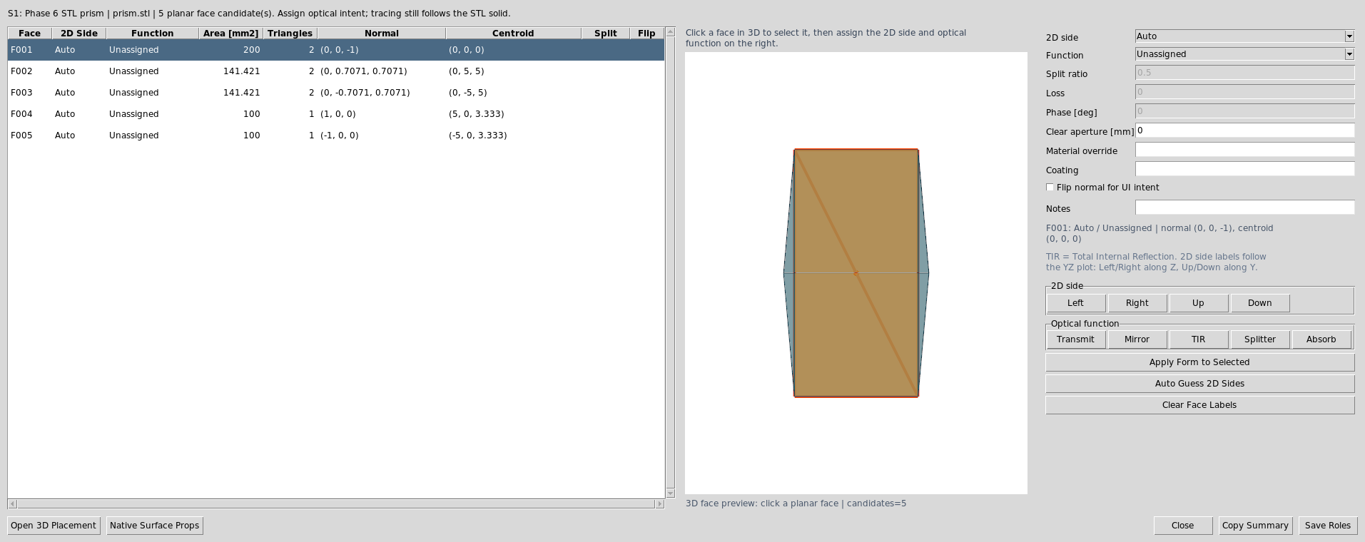
The implemented face-role slice is available through Actions -> Assign
CAD/STL Optical Faces. The dialog renders the actual STL/CAD mesh at the
current row pose and draws transparent selectable overlays plus outlines for
the planar face candidates. Click a coloured face in the preview to select
that candidate, then assign a 2D side and an Optical function with the
quick buttons or the detailed form on the right. A plain click selects; left
hold-drag rotates the preview
around the current focal point with fixed sensitivity, matching Open 3D instead
of VTK’s default accelerated trackball behaviour. Left/Right are along
the 2D layout Z direction and Up/Down are along Y; Front/Back
are available for full 3D orientation notes. By default, Save Roles also
uses the Input Port face as the input-face convention, snaps that face to
the current Path view or the outgoing traced segment after the previous table
surface, and writes the solved TiltX/Y/Z and DespX/Y/Z pose back to the
row. If those are unavailable it uses the nearest traced 3D ray; if no traced
ray is available, it falls back to the old row-plane convention: outward normal
-Z with incoming ray +Z. Save Roles first applies the currently
selected face form, so a separate Apply Form to Selected click is optional
for the active selection.
For arbitrary prisms, use Fit ref normal on one nonparallel face to fix the
remaining roll after the entrance face is aligned. For example, +Y normal
means the selected face normal should point upward in the layout; changing it
to -Y normal gives the corresponding Y-axis flip. 2D side remains the
plot/path label, while Fit ref normal is the 3D orientation constraint.
For vendor drawings with an off-center entrance point, use Input snap U/V
[mm] on the chosen Input Port face. Save Roles snaps that in-face
anchor point, not only the face centroid, to the active traced input ray.
Use Pick In 3D to click the previewed face and back-fill those U/V
values directly from the chosen world-space point. U prefers the
face-plane projection of local +Z; V is the orthogonal in-plane axis.
The face list remains available as a fallback and as a
compact audit table. The face list emulates cell wrapping from the current
column width because Tk’s native tree table does not wrap cell text by itself.
Drag a column separator to reflow the visible cells, or double-click a column
separator to auto-fit that column to its full content. The Uncoated face
mode uses ordinary glass/air Snell-Fresnel physics; total internal reflection
is then automatic when the incidence exceeds the critical angle. Split ratio is
only shown and editable for faces whose function is Partial Reflecting /
Transmitting; phase and loss are enabled only for face functions where those
quantities are meaningful. Diffuse transmitting/reflecting behavior is not yet
implemented on imported CAD/STL faces; use a Diffuse Object row when the
required physics is Lambertian or BRDF-based scattering. If one physical optical
interface appears as two CAD
faces, such as a split cube-beam-splitter interface, select both face rows with
Shift/Ctrl and press Splitter so the same function metadata is applied to
both candidates.
For chained CAD/STL work, the UI uses one output-port pose resolver for all views. A downstream CAD solid is displayed and traced from the upstream output port pose, so 2D silhouettes, Open 3D meshes, face-role overlays, and Image planes should stay aligned. If a chained solid looks different in 2D and 3D, that is a resolver bug rather than a drawing preference.
If the installed VTK package does not ship libvtkRenderingTk.so, the dialog
uses the Matplotlib/Tk 3D picker directly instead of first trying the broken
VTK/Tk widget path. This is expected for the standard pip VTK wheels: they ship
the Python vtkTkRenderWindowInteractor wrapper but not the native
libvtkRenderingTk.so Tk widget library.
The same dialog now includes a Virtual Internal Plane workbench for
cube-style beam-splitter CAD. After labeling the outer Left, Right,
Up, and Down faces, use Auto Cube Splitter Plane to derive a saved
45-degree internal diagonal with split, loss, phase, and aperture metadata.
The plane is previewed in 3D and stored alongside the face labels inside
OpticalSolidFaces.
Actions -> Assign CAD/STL Optical Faces opens the face table, 3D face
preview, side labels, and optical-function quick buttons for the selected
optical solid row.
The project devenv uses python313Packages.vtk from nixpkgs for the VTK
Python module and sets KRAKEN_VTK_TK_LIB_DIR to the same package’s lib
directory. kraken-install removes any pip-installed vtk wheel so the
venv does not shadow the Nix VTK build. Use devenv shell kraken-vtk-tk-check
to verify that the UI can see the native VTK/Tk widget.
For a non-devenv setup, install or build VTK with VTK_USE_TK=ON and make the
directory containing libvtkRenderingTk.so visible to the UI. KrakenOS
searches the VTK package directory, the Python lib directory,
/usr/local/lib, TCLLIBPATH, LD_LIBRARY_PATH, and the explicit
KRAKEN_VTK_TK_LIB_DIR or VTK_TK_LIB_DIR environment variables. Keep the
Python vtk module and libvtkRenderingTk.so from the same VTK build to
avoid ABI mismatches.
Assigned side/function labels are saved with the optical solid row as
OpticalSolidFaces metadata. Direct Open 3D assignments are drawn as
coloured face outlines only; the full face-role editor can still preview
face-centre/normal markers when that dialog is being used. Snap-to-ray pose
solving remains the next scene-object workflow step.
The future prism workflow should validate these cases before it is considered complete:
BK7 wedge-prism deviation with the expected media transition
right-angle prism total internal reflection
classic prism dispersion pose, including visible output steering
missed-ray and clipped-ray diagnostics on the selected solid
agreement between 2D slice, 3D view, ray inspector, and STEP ray-envelope export
For finite detector apertures, a ray that exits the modeled optical geometry but intersects the detector plane outside the active aperture is drawn to that plane and marked as a missed detector. This is a diagnostic terminal event: the ray is not counted as a detector hit, and the event/analysis CSV records the detector surface, miss radius, active half-aperture, projected distance, normal residual, and original kernel terminal reason.
Use Actions -> Detector Aperture Report when the plot shows clipped or
early-terminated rays near a detector. The report does not retrace rays and
does not infer detector state from the 2D drawing; it summarizes the active
SceneBundle ray-analysis records, so the numbers match Ray Inspector,
Ray Events CSV, detector-miss crosshair overlays, and the detector aperture
rows in the normal results panel.
Ray Inspector CSV also includes normalized per-ray aperture status fields next
to the raw detector-miss event metadata.
In Open 3D, detector active-footprint overlays remain scene geometry, but
detector-miss crosshairs follow Show rays because they are ray diagnostics.
Escaped ray tails are capped in 2D and Open 3D display only, using a
scene-envelope continuation long enough to show the output direction without
collapsing YZ/XZ/XY autoscale. Missed-detector diagnostics are capped within
the detector plane and do not draw endpoint spheres, so a displayed miss cannot
look like an absorptive stop away from a surface. The underlying terminal event
still records the full detector-plane projection, miss distance, and kernel
termination reason.
Vendor CAD caveat: a downloaded cube beam-splitter STEP is usually mechanical
geometry, not a complete optical prescription. Import it for external cube
boundaries/placement, then add a table Beam Splitter surface or use
Insert Component Below -> Cube Beam Splitter for the internal 45 degree
coating/path physics. The CAD mesh alone cannot infer coating ratio, phase, or
cemented internal splitter behavior.
The new virtual internal plane metadata helps author that missing diagonal and
keep it attached to the imported CAD row, but current tracing still follows the
closed STL/CAD envelope. Treat the virtual plane as saved authoring intent and
3D preview data for now; use the validated cube primitive or a real
Beam Splitter row when you need traced reflected/transmitted branches today.
Face roles do not move or center a CAD/STL solid. They say which imported faces
are optically meaningful. To put the cube/prism on the beam, use
Actions -> 3D Place/Orient Selected CAD/STL Solid and then
Center Row->Optical Axis in the 3D inspector, or edit row TiltX/Y/Z and
DespX/Y/Z directly. A future snap solver should combine the selected input
face, a clicked beam/path, and a roll/output constraint to solve this placement
automatically.
The placement dialog now provides the first explicit anchor/roll slice of that future solver:
Anchor facechooses one assigned optical face orAuto.Roll constraintcan use the saved side labels as a simple roll guide.Face -> +ZorFace -> -Zaligns the chosen face normal to the layout optical axis, then recenters that face on the row plane.Face -> RayorFace <- Rayaligns the chosen face to the currently selected traced ray and snaps the face anchor onto the nearest picked point on that ray.Face -> PathorFace <- Pathaligns the chosen face to the currently selected Path-view frame and snaps the face anchor onto the nearest point on that traced path axis.Anchor X/YandAnchor On Rowshift the selected face centroid instead of the whole mesh bounding box.
The selected ray can come from the 2D plot, 3D view, or Ray Inspector. The
current path frame comes from the top Path dropdown above the 2D plot. This
is still not a full output-constrained prism solver, but it is now a real
path-frame placement bridge between saved face metadata and traced scene data.
Virtual internal planes are drawn in the embedded 3D inspector and CAD placement preview as translucent diagonal overlays with a normal arrow, so the stored cube-splitter authoring intent remains visible while you place the solid.
The mesh diagnostics report checks triangle count, bounds, open boundary edges, non-manifold edges, degenerate triangles, signed volume, and likely face winding. It cannot certify optical design intent; it only catches the common mesh defects that make a closed prism fail to steer rays according to Snell/reflection laws.
Placement workflow
After importing a CAD/STL solid, first complete the automatically opened face
assignment dialog. If the saved Left input convention is not enough, select
that row and open Actions -> 3D Place/Orient Selected CAD/STL Solid for
manual pose controls. If embedded VTK/Tk is available, the embedded 3D
inspector highlights the solid row and opens a
CAD/STL placement handler right-side panel inside the 3D inspector. The
panel stays visible when the main UI is tiled or fullscreen and does not cover
the 3D scene. If only the legacy PyVista viewer is available, the bottom
STL row contains the placement buttons. Both paths
write the row TiltX, TiltY, TiltZ, DespX, DespY, and
DespZ values while the 3D view refreshes.
For scene authoring, row pose is now accompanied by optional
ScenePlacement metadata. This stores linear snap spacing, angular snap
step, grid visibility, and the intended placement anchor on the surface row,
then publishes the same data as ScenePlacement3D records in SceneBundle
and the Non-Sequential Scene Graph. Open 3D uses the selected or first visible
placement record to report active spacing, extent, snap state, and placement
count in the viewer, but the visible cube/grid planes are suppressed so they do
not cover CAD faces during assignment. Plain Object/Image reference targets stay
target records and do not create default placement handles; stale
ScenePlacement metadata on those reference rows is ignored, and the
reference marker size follows the editable row diameter. The colored translation
handles move the selected row along global X/Y/Z by
ScenePlacement.snap_mm when snap is enabled, or by the placement spacing
when snap is off. The rotation handles use one half-arc per global X/Y/Z
axis with sharp opposed cone arrowheads. Imported STEP overlays use separate
+90 and -90 end-arrow commands, while row placement handles apply a
world-axis rotation matching the visible ring by ScenePlacement.snap_deg
when snap is enabled, or by 15 degrees when snap is off; the Open 3D
Rotation handles checkbox hides these arcs when a clear face-picking view
is needed. These actions write
the normal row DespX/Y/Z and TiltX/Y/Z fields and record the last placement
edit in ScenePlacement metadata. Dragging a placement handle accumulates
screen motion and applies repeated snap steps through the same row-backed
services; clicking without dragging remains the one-step precise fallback.
Snap Row->Target adds the first target-surface constraint tool: click the
button, choose the movable surface/CAD row or face,
then click the target row or face. The editor solves the translation in world
coordinates, writes the normal row DespX/Y/Z fields, and records the
target_surface constraint in the row’s ScenePlacement metadata.
Orient Row->Target follows the same two-click pattern but solves rotation:
the selected row or face normal is aligned to the target row or face normal,
the normal row TiltX/Y/Z fields are written, and the solved
target_normal constraint is recorded in ScenePlacement metadata.
Orient Row->Ray uses the same row-backed rotation service for traced data:
click the button, choose the movable surface/CAD row or face, then click a
traced ray. The selected row or face normal is aligned to the nearest segment
direction of that ray, the normal row TiltX/Y/Z fields are written, and
target_ray metadata records the ray index, target vector, nearest point,
branch path, source id, and residual angle error.
Orient Row->Source and Orient Row->Path are immediate commands for the
currently selected or picked row/face. Orient Row->Source aligns the row or
face normal to the Source panel aim vector and records source_vector
metadata, including source origin, direction, model, and residual angle error.
Orient Row->Path aligns the row or face normal to the current Path-view
frame near the row/face and records path_frame metadata, including branch
path, sample count, origin surface, nearest target point, target vector, and
residual angle error.
Orient Row->CAD Axis uses the toolbar +X/-X/+Y/-Y/+Z/-Z selector as a
row-local axis target after the row’s current world transform is applied. It
then writes the solved TiltX/Y/Z and records local_axis metadata,
including the target axis row, axis label, axis vector, target vector, and
residual angle error. Orient Row->Scene Source aligns the selected row or
face normal to a Scene Source Manager source. If a source row is selected in
the editable table, that source is used; otherwise the first enabled physical
source is used. The command records scene_source_vector metadata,
including source id/name, origin, direction, model, ray count, target vector,
and residual angle error.
The named normal selector uses the first matching scene target for
Active target, Detector, or Object. Preview Normal reports the
target row, role, normal vector, target point, and current angle error without
changing the prescription. Orient Row->Normal applies the same row-backed
rotation service and records active_target_normal, detector_normal, or
object_normal metadata, including the target row/id/name/role, target
point, target normal, and residual angle error. These diagnostics appear in the
Non-Sequential Scene Graph and CSV export beside the row-backed
ScenePlacement record.
Use Fit+Z, Fit+X, or Fit+Y to state which STL-local axis should
become the layout optical axis (layout +Z). For example, use Fit+Z when
the prism was modeled along local Z, or Fit+X when the CAD model’s length is
local X. Center translates the rotated mesh so its X/Y bounding-box centre
lies on the optical axis. Front translates the rotated mesh so its minimum Z
bound sits on the selected row plane.
The embedded handler also provides one-click X/Y/Z +/-90 rotations,
Center X/Y, Front On Row, and Done -> 2D. Closing only the handler
keeps the 3D view open; pressing Done -> 2D refreshes the 2D plot from the
same row pose.
If OpticalSolidFaces metadata is present on the selected row, the 3D view
draws assigned side/function labels as coloured markers:
grey: side-only or unassigned function
blue:
Transmit/Portand legacyTIRmetadatasilver:
Mirrorred:
Beam Splitterblack:
Absorber/Mechanical
Use the Faces... button in the embedded 3D inspector, or Assign Optical
Faces in the isolated placement preview, to reopen the role editor for the
selected solid. After saving roles, press Refresh or Render to redraw
the markers.
Use Center Row->Optical Axis when manual CAD placement is hard to judge
visually. Click the button, click the surface/CAD row to move, then click the
persistent dotted Optical Axis guide. The workflow hides regular rays during
the pick but does not hide the optical-axis guide. During the first click, the
guide is ignored by the source picker so an axis drawn through a solid does not
block selection of the row surface or imported STEP face underneath it, and the
hovered row or STEP face is highlighted before the click. Show rays only
controls traced rays; the dotted optical-axis guide remains visible and
pickable. During the second click, the dotted guide is highlighted as soon as
the pointer is near it so the user can see which optical axis will be selected
before committing the snap.
If the first click lands on an imported, unpromoted STEP face instead of a
KrakenOS row, the workflow becomes STEP face normal-to-axis alignment: the face
normal and feature center are cached, and the second click on the dotted guide
rotates/translates the imported STEP overlay so that face lands on the optical
axis. This is intentionally separate from row centering because
unpromoted STEP overlays do not yet own row metadata or DespX/Y/Z fields.
For ordinary rows the editor computes the selected row’s surface plane, finds
where the picked guide crosses that plane, and writes the row
DespX/Y/Z values so the surface center moves onto the optical axis without
changing the row orientation. For file-backed CAD/STL solids with saved
OpticalSolidFaces metadata, the same action now prefers the best assigned
optical-face anchor
instead of the generic row center. That makes optical-axis placement more useful
for prisms and vendor CAD where the meaningful optical entry face is not the
mesh centroid. This is still an alignment aid; use Fit Axis and Min Z On
Row first when the CAD solid also needs orientation or front-face placement.
KrakenOS placement semantics are important:
the previous row’s
Thicknesssets the selected CAD/STL row’s nominal Z stationTiltX/Y/Zrotate the STL mesh about the STL file originDespX/Y/Ztranslate the rotated STL meshAxisMoveaffects transform propagation to later rows, not the local STL orientation itself. Open 3D-promoted and newly imported optical CAD/STL solids default toAxisMove = 0because they are scene objects; explicit output ports are the workflow for moving downstream follower rows onto a traced prism exit.
STEP and CAD overlays
STEP support is beyond the 2021 manual but is available in the UI for real hardware context:
lens/camera/LED STEP import from the main File menu, plus arbitrary optical STEP import directly from the Open 3D
CAD / target -> Import STEPmenu. The arbitrary optical import uses a separateopticaloverlay slot and does not replace an existing lens STEP overlay.Show Rays and Trace Now keep arbitrary imported optical STEP overlays display-only until the user explicitly places/snaps them. Once placed, a supported axisymmetric lens STEP is traced through reconstructed KrakenOS native analytic rows; unsupported solids still use the mesh-backed
Solid_3d_stloptical-solid path.imported STEP carry placement in Open 3D: a newly imported optical STEP is selected and carried by the cursor immediately until the next click drops it. If the pointer is outside the VTK canvas when the file dialog closes, the first in-canvas pointer motion attaches the STEP center to the cursor plane. To move an already-imported STEP, hold the pointer on the STEP body briefly, or start dragging on the STEP body, until the carry anchor snaps to the STEP center and an in-scene grip cursor appears there. Release to drop and commit the placement. The OS pointer is not warped during hold-drag because synthetic Tk/VTK motion can be fed back into the drag loop and make the component jump. The carry path projects the cursor ray onto a drag plane through the STEP center and moves continuously on that plane. The old cube lattice and carry snap-step controls are removed.
Ctrl+dragkeeps left-drag available for camera rotation, andEsccancels active carry or pick modes. Use the STEP face-to-axis workflow after free placement: click a planar STEP face, then click the persistent dottedOptical Axisguide. During that second click mode, arbitrary rays, surfaces, and STEP faces are ignored so the face normal can only align to the optical-axis guide.row-backed CAD/STL optical solids can also be centered on an optical axis by first clicking the exact face to use as the anchor and then clicking the dotted
Optical Axisguide. Repeating the workflow with another picked face changes the centering anchor without editing side labels.direct Open 3D right-click face assignment writes physics intent immediately. New optical CAD/STL imports default detected faces to
Uncoatedinteraction surfaces, so a plain glass-air boundary already uses Snell/Fresnel/TIR physics. Hovering a row-backed face shows a small badge with the current face function and port role. Manual assignments such asFull Reflectingor an explicitly confirmedUncoatedface are shown as non-pickable surface tints, while automatic default faces keep the simple body look. The row-backed STEP body remains transparent after assignment and when rays are visible, rather than switching to an opaque wireframe mesh. Explicit input/output ports remain available in the full face-role editor for port-chain workflows.STEP promotion reserves positive axial table thickness from the placed STEP world bounds. This matters when the layout starts with only Object and Image: the downstream Image/detector row is pushed behind the inserted optical solid instead of staying coincident with the prism entrance and terminating rays before they enter the CAD body.
CAD axis offset picking
selected STEP overlay rotation through in-scene coloured
X/Y/Zrotation handles around the selected lens, optical, camera, or LED STEP component; hovering an end arrow highlights it, and clicking applies a persistent+90or-90world-axis step immediately around the component center without opening a floating popupselected CAD/STL row placement through a click-open
CAD/STL placement handlerwith axis-fit, rotation, centering, front-plane, andDone -> 2Dactionsactive 3D workflow badges for
Center STEP Axis,Obj->LED,Center Row->Optical Axis,Snap Row->Target,Orient Row->Target,Orient Row->Ray, andSource Targetpick modesimmediate selected-row orientation commands for
Orient Row->Source,Orient Row->Path,Orient Row->CAD Axis, andOrient Row->Scene SourceSTEP export
external camera overlay workflows
When imported vendor STEP CAD is present, Export 3D STEP preserves the
original imported STEP BReps, applies the same placement transform used by the
3D view, and adds only the outer traced ray envelope as thin solid STEP tubes.
The ray envelope is exported as renderable solid geometry because several CAD
viewers import STEP wire curves but do not display them by default. This keeps
mechanical review focused on clearance and beam footprint instead of every
individual preview ray. File size is expected to be at least the sum of the
imported vendor STEP files plus the ray envelope tubes and analytic optical
surfaces.