Case Study 19: Galvo F-Theta Laser Scanner
Goal
This case study walks through the built-in Galvo F-Theta Laser Scanner
layout as a scanner design workflow:
load the common layout preset;
read the Gaussian laser source, beam-expander, galvo mirror, F-theta lens, and scan-plane rows as one folded scene;
understand the galvo scan-overlay angle convention;
inspect detector power and branch-field snapshots at the scan plane;
separate integrated scanner debugging from standalone F-theta lens prescription validation.
The static snapshots in this tutorial are generated from the common layouts with:
python -m KrakenOS.UI.render_layout_snapshot --layout "Galvo F-Theta Laser Scanner" --mode 2d --output docs/source/_static/tutorials/galvo_f_theta_laser_scanner/01_folded_layout_yz.png --dpi 150
python -m KrakenOS.UI.render_layout_snapshot --layout "Galvo F-Theta Laser Scanner" --mode detector_map --output docs/source/_static/tutorials/galvo_f_theta_laser_scanner/02_detector_map.png --dpi 150
python -m KrakenOS.UI.render_layout_snapshot --layout "Galvo F-Theta Laser Scanner" --mode branch_field --output docs/source/_static/tutorials/galvo_f_theta_laser_scanner/03_branch_field.png --dpi 150
python -m KrakenOS.UI.render_layout_snapshot --layout "F-Theta Lens 50mm Figure 8" --mode 2d --output docs/source/_static/tutorials/galvo_f_theta_laser_scanner/04_standalone_f_theta_lens.png --dpi 150
Validate the page, assets, and current common-layout angle convention with:
python -m KrakenOS.UI.validate_galvo_f_theta_case_study
Load The Preset
Start the UI with
python -m KrakenOS.UI.layout_editor.Choose
Layouts -> Sources / Illumination -> Galvo F-Theta Laser Scanner.Confirm these left-panel settings:
Source model       = Gaussian beam
GB input mode      = Diameter + divergence
GB diameter [mm]   = 1.0
GB full div [mrad] = 2.0
GB M2              = 1.1
Wavelength [um]    = 0.65
Trace mode         = Folded Preview
Folded reach       = Display compatibility
Ray Count          = 9
The source is a physical Gaussian source, not an abstract field sample. The
scanner scene then sends representative rays through a two-lens beam expander,
reflects them from the galvo mirror, and traces the folded leg through the
F-theta lens to the scan plane. Display compatibility is deliberately
explicit here: the folded display path is allowed to provide detector reach for
this legacy folded scanner preview, while the exported ray records still mark
that terminal source as folded-display provenance.

The scanner is a scene workflow. The beam expander, mirror, F-theta lens, and scan plane are physical entities along one traced path.
Read The Rows
The preset table is intentionally explicit. The row groups are:
Group |
Rows |
Purpose |
|---|---|---|
Laser source |
|
Defines the Gaussian launch plane and source direction. |
Beam expander L1 |
two refractive rows |
Negative lens that starts the expansion. |
Beam expander L2 |
two refractive rows |
Positive lens that recollimates the beam near the galvo/stop. |
Galvo mirror |
one |
A 45 deg fold. Its |
F-theta Figure 8 lens |
eight refractive rows |
The 50 mm, 40 deg full-field prescription transcribed from
|
Scan plane |
|
Flat scan/focus plane used by detector and branch-field analyses. |
Click Update. The YZ view should show the beam propagating along +Z,
folding downward at the galvo mirror, then passing through the F-theta lens to
the scan/focus plane.
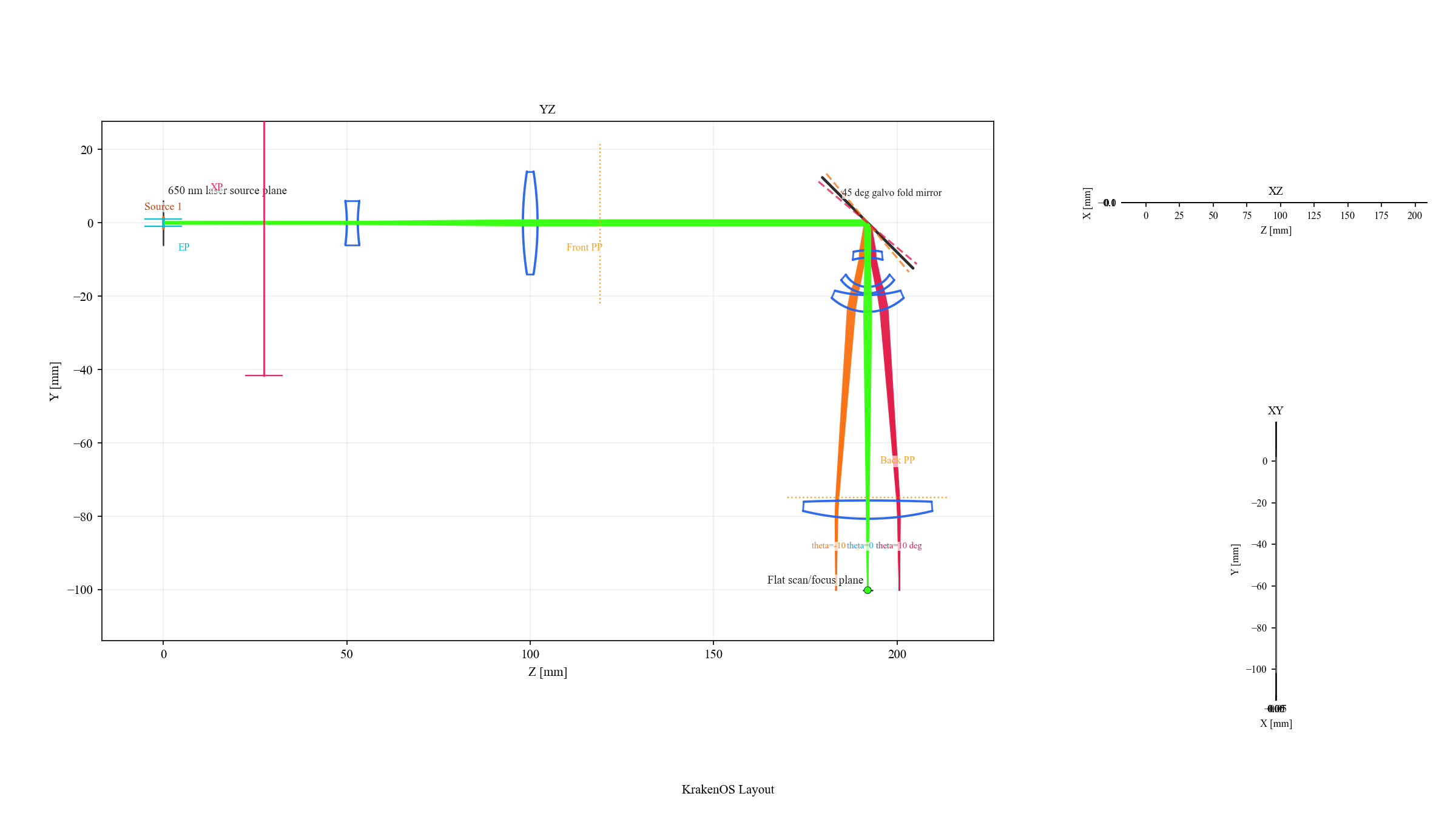
The green center bundle is the nominal 45 deg galvo pose. The orange
and red bundles are the preset scan-overlay poses.
Use The Galvo Scan Overlay
The mirror row’s TiltX cell is a mirror-slant value. It is not the F-theta
field angle. In the current common layout, the nominal fold is:
Galvo mirror TiltX = 45
To draw a conservative -10, 0, +10 deg optical scan overlay, enter:
TiltX = 40,45,50
The equivalent range syntax is:
TiltX = 40:50:5
Around the nominal 45 deg fold, the reflected optical scan is approximately
twice the mirror slant change. For the nominal full Figure 8 -20, 0, +20 deg
optical scan, use:
TiltX = 35,45,55
The middle value remains the nominal row value. The full list is stored as display/path metadata and draws additional folded rays without duplicating prescription rows.

The table value is mirror slant. The reflected beam angle changes by about twice the slant change from the nominal fold.
Check The Scan Plane
Use detector analysis to verify that traced power reaches the scan/focus plane:
Keep the preset loaded.
Click
Detectoror render thedetector_mapsnapshot.Inspect the map annotation: it should name the
Flat scan/focus planeand report nonzero accumulated power.
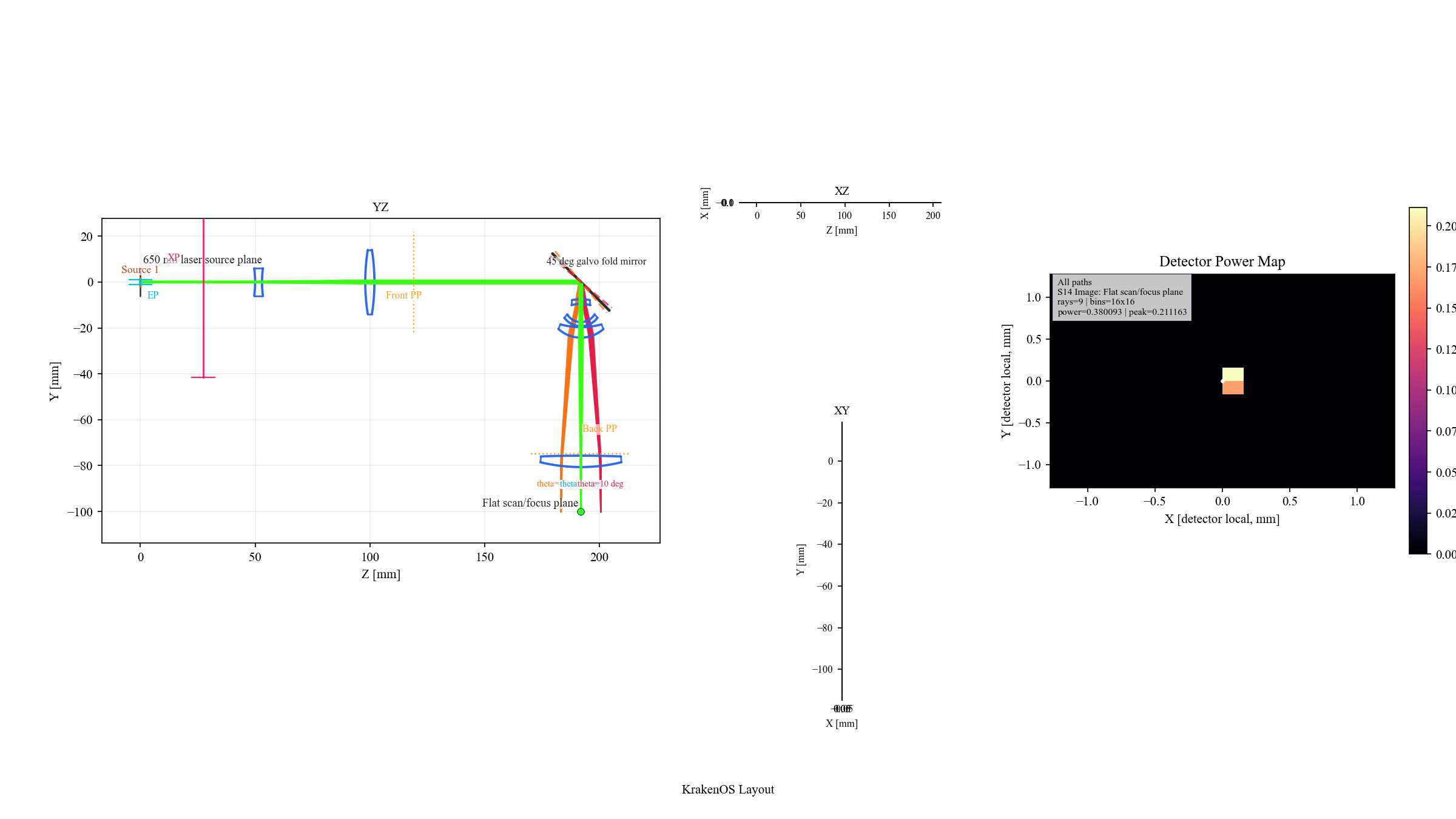
The default preset uses only nine representative rays, so the detector map
is intentionally sparse. Increase Ray Count and detector bins when you
need a smoother engineering map.
Use branch-field analysis when you want the coherent field grid rather than a ray-hit power histogram:
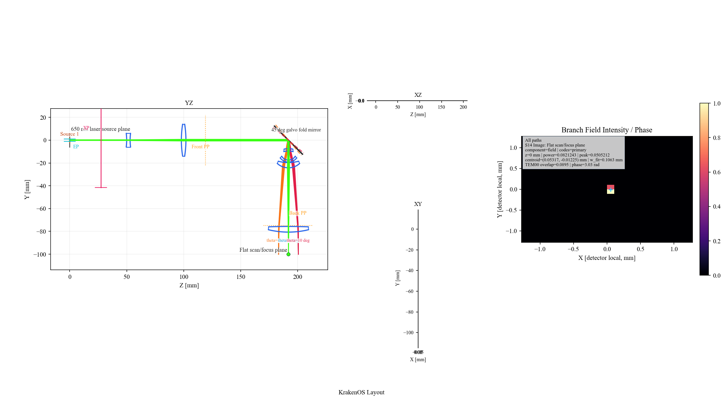
Branch field promotes the detector samples into an intensity/phase grid and reports the branch-local Gaussian-q fit on the scan plane.
Validate The F-Theta Lens Alone
If the integrated scanner spot is not where you expect, do not start by editing the fold mirror or beam expander blindly. First isolate the lens prescription:
Load
Layouts -> Components -> F-Theta Lens 50mm Figure 8.Keep
Object Mode = Infinity.Keep
Field Type = AngleandField Value = 20.0.Click
Update.
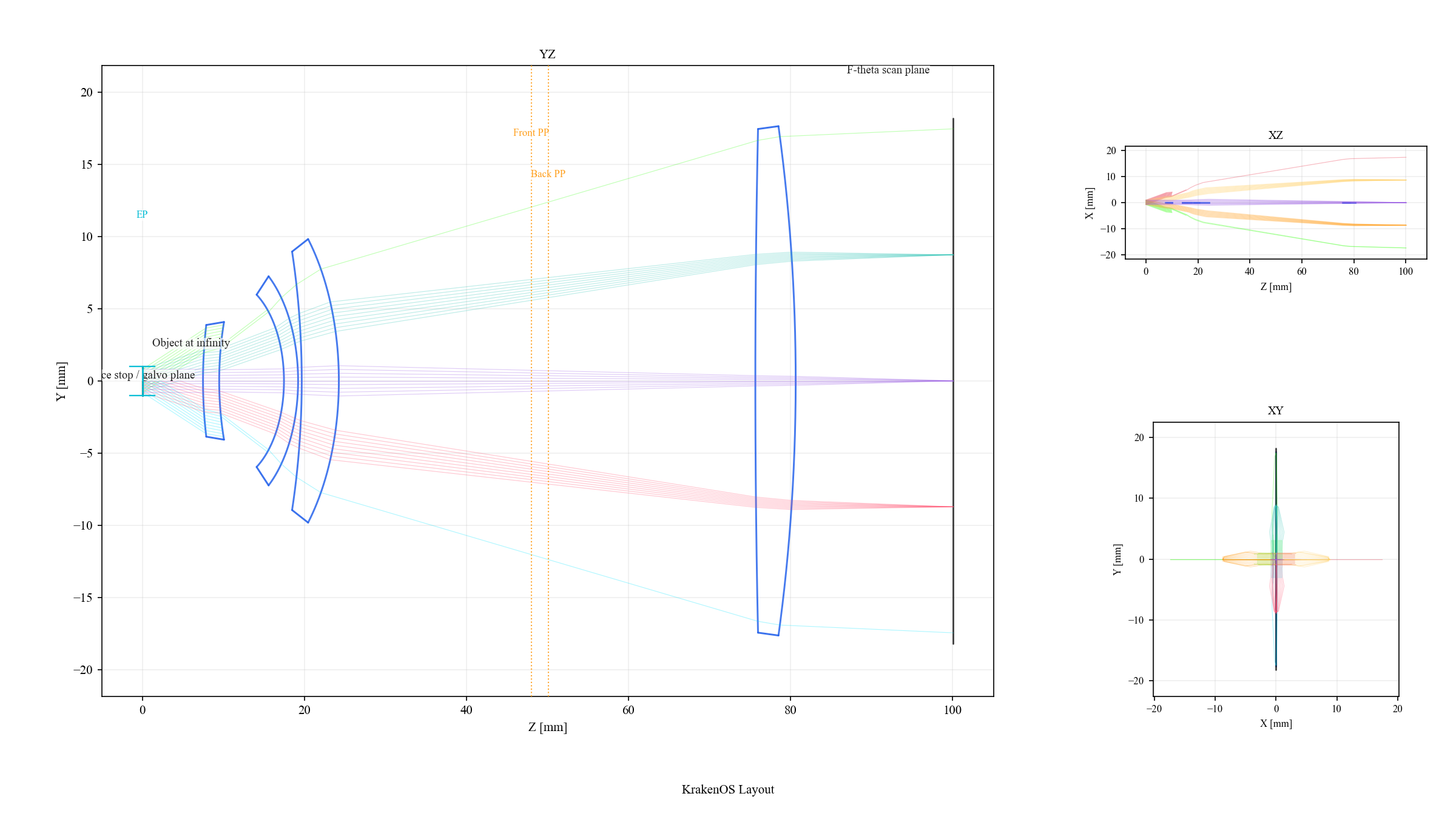
The standalone lens layout removes the Gaussian source, beam expander, and fold mirror. Use it to verify the lens prescription before debugging the integrated scanner bench.
After the standalone lens is correct, return to the scanner and adjust the upstream bench in this order:
Gaussian source diameter, divergence, and
M2.Beam-expander spacing and lens powers.
Galvo
TiltXnominal fold and overlay values.Scan plane location or detector size.
Why This Is Non-Sequential-First
This case uses Folded Preview because the scanner is not a simple axial
ordered lens train. The source, mirror, lens, scan plane, and path metadata are
scene entities. The YZ/XZ/XY panes are projections of traced 3D data, and the
detector/branch-field analyses read the selected terminal surface rather than
running a separate 2D simulation.
For new scene work, prefer Non-Sequential Preview or Auto with physical
sources and detector surfaces. Keep Folded reach = Trace events unless the
layout is intentionally using folded-display detector reach as a compatibility
preview.
The standalone F-theta lens remains a valid sequential special case. Use it for classic lens-prescription checks. Use the integrated galvo scanner when the question includes the physical source, beam expander, fold mirror, scan overlay, detector, or path metadata.
Common Checks
Use these quick checks when the scanner view looks wrong:
Symptom |
Check |
|---|---|
The spot misses the scan plane |
Validate the standalone F-theta layout first, then check beam-expander collimation at the galvo/entrance stop. |
Scan overlay looks mirrored |
Confirm whether the current layout uses a positive |
Detector map is blocky |
Increase |
XZ or XY appears collapsed |
The preset is mostly a YZ folded bench. XZ and XY are still valid projections, but most geometry lies in the YZ plane. |
Wavefront comparison does not match a Zemax screenshot |
Use |
What This Proves
The case study exercises the North Star workflow:
the scanner is loaded as a scene with physical source and folded path metadata;
2D views are projections of the traced scene;
detector and branch-field results report on the selected scan plane;
the sequential F-theta lens is still available as an ordered-prescription special case when that is the actual analysis question.