Case Study 8: Source/Object Split Through A Beam Splitter
Goal
This case study demonstrates a source/object workflow where the illumination source is not the Object row:
load a right-angle beam-splitter illumination layout;
verify that
Src1is an independent illumination source row;trace source light through a 45 degree beam splitter to an object target;
follow the object-return path to a camera sensor;
use
Source Illumination Reportto audit source throughput at both the object and camera targets;run a detector power map at the camera plane.
The screenshots in this tutorial are generated from the live Tk UI with:
python -m KrakenOS.UI.capture_right_angle_beam_splitter_case_study_screenshots
Load The Layout
Start the UI with
python -m KrakenOS.UI.layout_editor.Choose
Layouts -> Beam Splitters / Folds -> Right-Angle Beam-Splitter Illumination.Keep
Trace mode = Non-Sequential Preview.Keep
NS probabilistic coating splitoff.
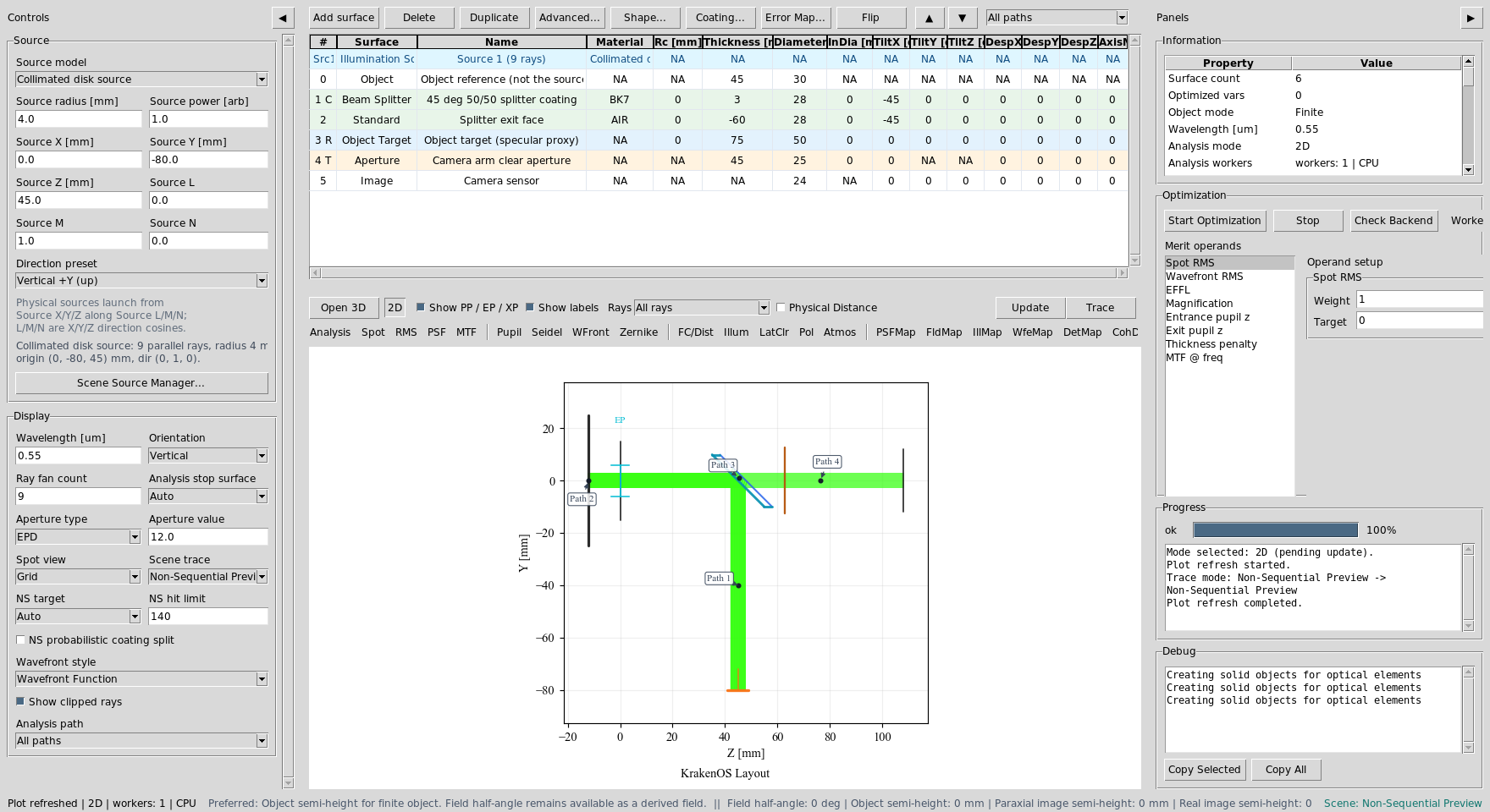
The first visible row is Src1. That row is a scene source, not a KrakenOS
surface. The Object row is reference geometry only. In this preset, the
physical source starts at (0, -80, 45) mm and points along +Y toward the
45 degree splitter.
Src1 launches the illumination. The Object row no longer has to be the
ray source.
Read The Physical Paths
Click Update. The schematic shows the source entering from the side, the
splitter sending the useful reflected branch to the object target, and the
returning object branch transmitting toward the camera sensor.
The useful path is not a straight object-to-image sequential chain. It is a folded non-sequential source path.
Use Path View
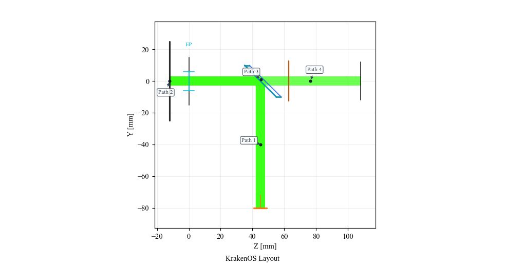
After Update, open the table toolbar Path view dropdown and select:
Path 2: 45 deg 50/50 splitter coating to 45 deg 50/50 splitter coating via Object target (specular proxy)
This isolates the object-return leg. The current Object Target row is a
specular proxy: it lets the beam return through the splitter and camera path.
Use a Diffuse Object surface when the required physics is Lambertian or
BRDF scattering rather than a mirror-like proxy.
The object-return path is separate from the source and camera legs.
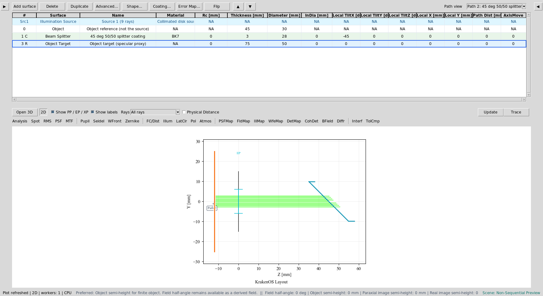
Now select:
Path entry containing: 45 deg 50/50 splitter coating to Camera arm clear aperture via Splitter exit face
This isolates the useful camera leg after the returning object branch passes through the splitter. The exact path number may change as terminal diagnostic branches are inserted, so use the discovered path label that reaches the camera arm clear aperture through the splitter exit face.
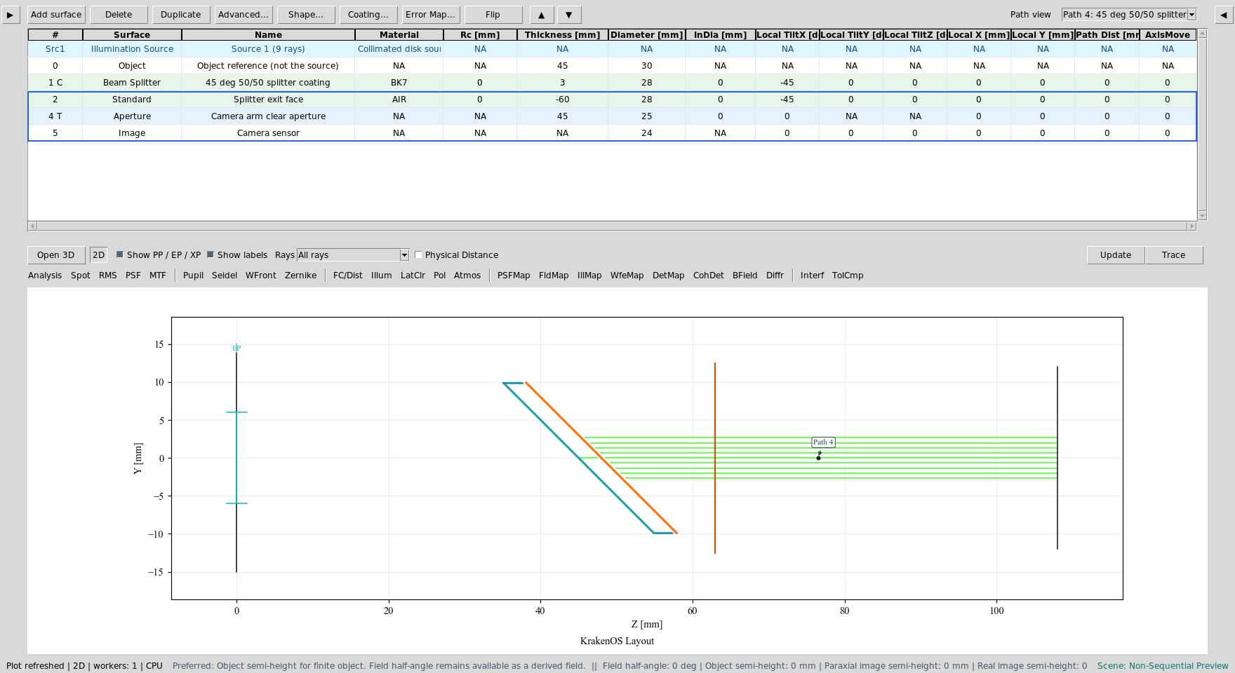
The camera path contains the splitter exit face, clear aperture, and Image sensor.
Audit Source Illumination
For the report screenshots, use:
Ray fan count = 121
Source radius [mm] = 8.0
Detector bins = 96
Path view = All paths
Choose Actions -> Source Illumination Report. Set Target to:
3: Object target (specular proxy)
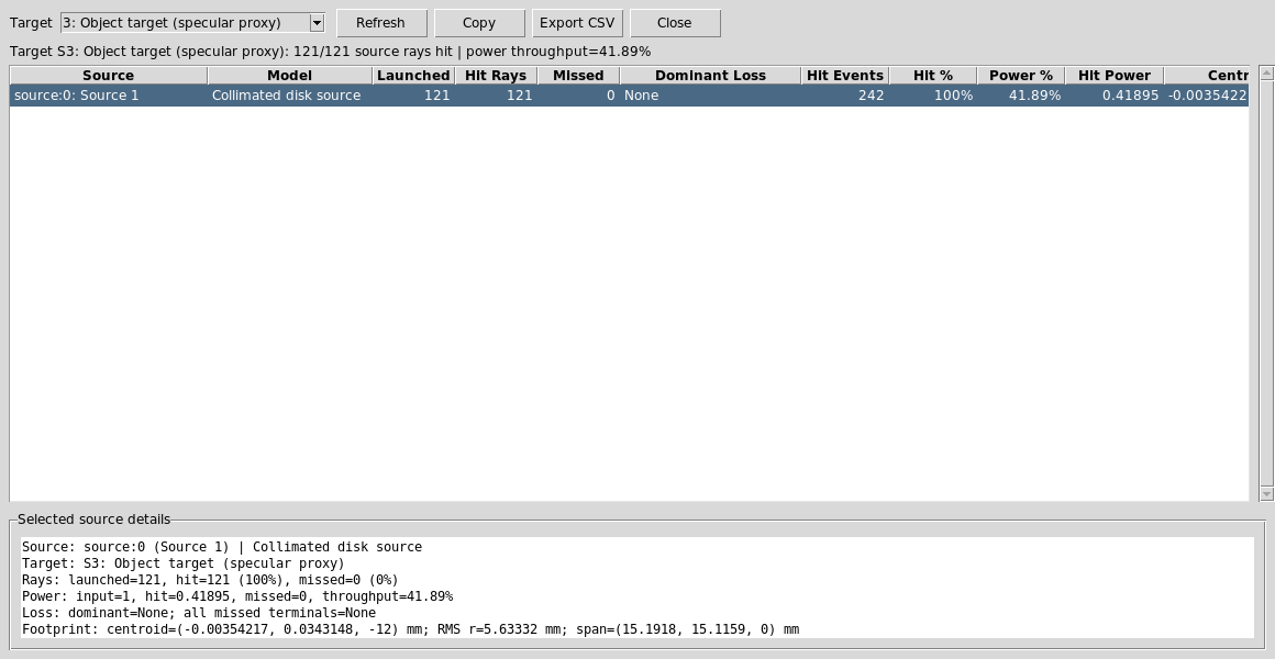
The report verifies that source rays reach the object target and reports the power throughput after the first beam-splitter interaction.
Now change Target to:
5: Camera sensor
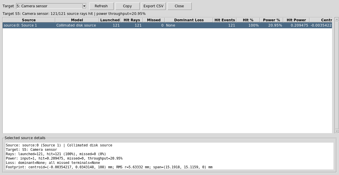
The camera report verifies that the object-return path reaches the Image plane. The lower throughput is expected because the useful path has passed through two 50/50 splitter interactions.
Run The Camera Detector Map
Set the analysis controls to:
Analysis path = Output: Detector output port
Analysis surface = 5: Camera sensor
Click DetMap and Update.
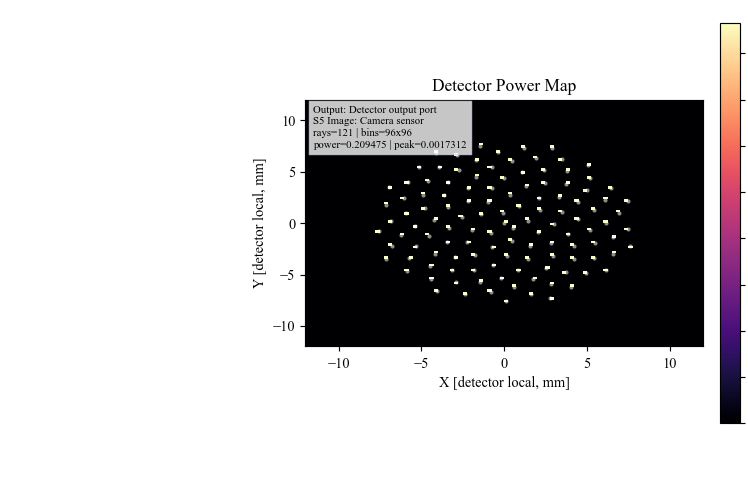
DetMap shows the final camera-plane power distribution for the useful
source-to-object-to-camera path.
Run The Python Example
The same layout has a scriptable example:
python KrakenOS/Examples/Examp_Right_Angle_Beam_Splitter_Illumination.py
The script prints the source origin/direction and a per-ray trace summary, including whether each ray hits the object target and reaches the camera.
What This Proves
This case study exercises the source/object separation needed for inspection, projector, and coaxial-illumination workflows:
the Source panel and
Src1scene row define illumination;the Object row is reference/object geometry, not the ray launcher;
a 45 degree splitter can route illumination to the object;
an object-return branch can pass back through the splitter to a camera;
source-hit records preserve throughput and footprint diagnostics;
detector analysis can be run on the resulting camera path.
Common Mistakes
I moved the Object row and expected the source to move.Move the source controls or open Scene Source Manager. Object geometry and illumination source are separate scene entities.
I expected diffuse object scattering from Object Target.Object Targetis currently a specular reflective proxy in this preset. UseDiffuse Objectexamples for Lambertian or rough scattering.The camera power is about half of the object-target power.That is expected for this deterministic 50/50 splitter path. The useful beam reflects once to reach the object and transmits once to reach the camera.
Path view changed the visible rows.Path view filters the table and plot. It does not renumber KrakenOS surface indices or convert source rows into surfaces.