Case Study 14: Vendor Prism CAD Import And Face Placement
Goal
This case study shows the production-facing CAD workflow for an off-the-shelf vendor prism:
keep the vendor STEP, IGES, drawing, and curve documentation with the project;
import the STEP body as a KrakenOS
Solid_3d_stloptical row;inspect the generated mesh before trusting the trace;
label candidate optical faces as input, output, fold, or mechanical faces;
solve a first table pose from one selected CAD face;
keep the final warning visible: face labels are authoring metadata and must be checked against the vendor drawing before production.
The screenshots in this tutorial are generated from the live Tk UI with:
python -m KrakenOS.UI.capture_vendor_prism_case_study_screenshots
The validation script uses the same files:
python -m KrakenOS.UI.validate_vendor_prism_42779
Bundled Vendor Files
The tutorial uses a small Edmund 42779 prism package under:
attachment/prisms/Penta/step_42779.step
attachment/prisms/Penta/iges_42779.igs
attachment/prisms/Penta/prnt_42779.pdf
attachment/prisms/Penta/CURV_42779.pdf
attachment/prisms/Penta/edrw_42779.eprt
The STEP file is the preferred import source. The IGES file is kept as a fallback reference. The PDF files are not used by the ray trace; they are kept so the user can verify which faces are intended optical ports, which surface is coated or folded, and whether the imported scale matches the drawing.
Load The Vendor CAD Prism
Start the UI with
python -m KrakenOS.UI.layout_editor.Choose
File -> Import Optical CAD/STL Solid....Select
attachment/prisms/Penta/step_42779.step.The CAD/STL optical-face assignment dialog opens automatically after the row is inserted.
Keep the row material as the intended optical glass, for example
BK7if the drawing and stock number support that assumption.Set
Trace mode = Non-Sequential Preview.Click
Update.
The generated case-study screenshot builds the same table directly so the documentation is reproducible:
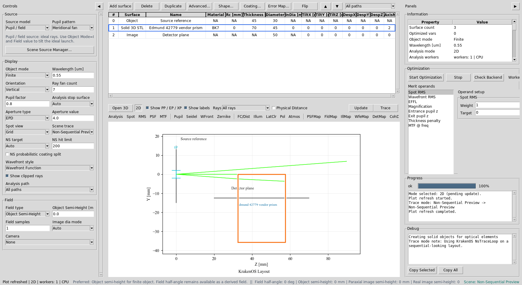
The row stores the cached mesh path, the original STEP source path, the IGES fallback path, the material, and the editable KrakenOS pose fields.
Set Source Divergence
Set Object Mode to Finite in the left panel, then use
Scene Source Manager... in the Source panel to edit source divergence. For
the default ideal workflow, keep Model as Pupil / field and edit
Cone half-angle [deg] in the manager. In Open 3D this launches a
deterministic filled 3D angular-pupil cone from the object-field point. With
Field = 0 that point is the object center.
For physical source-object split workflows, choose a physical source model such
as Random point cone, Random circle source, Random square source, or
Random line source in the manager. The same divergence control is a
half-angle, so a displayed value of 5 means a full cone angle of
10 deg.
For a laser-style Gaussian source, choose Source model -> Gaussian beam and
GB input mode -> Diameter + divergence. Enter the source-plane
GB diameter [mm] and the manufacturer-style GB full div [mrad]. That
Gaussian field uses full-angle divergence in milliradians, while the geometric
cone source uses half-angle degrees.
Inspect The Converted Mesh
Choose Actions -> Inspect Optical CAD/STL Solids before using any imported
body for optical decisions.
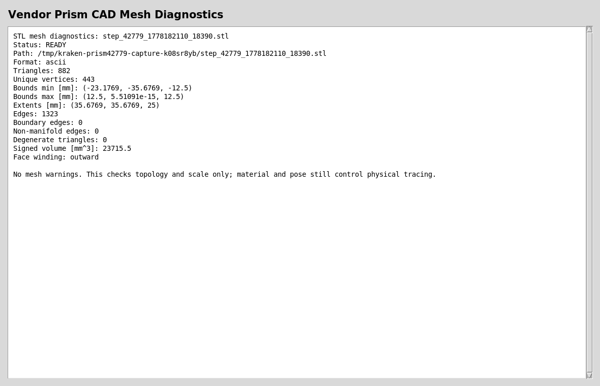
For this prism the converted STEP mesh is closed, finite, outward wound, and
trace-ready. The extents are roughly 35.7 x 35.7 x 25 mm, which is a
useful sanity check against the drawing.
A trace-ready report does not prove that the optical intent is correct. It only proves that the mesh is a usable closed solid for non-sequential intersection. You still need to verify the material, coated/fold face, and input/output faces against the vendor drawing.
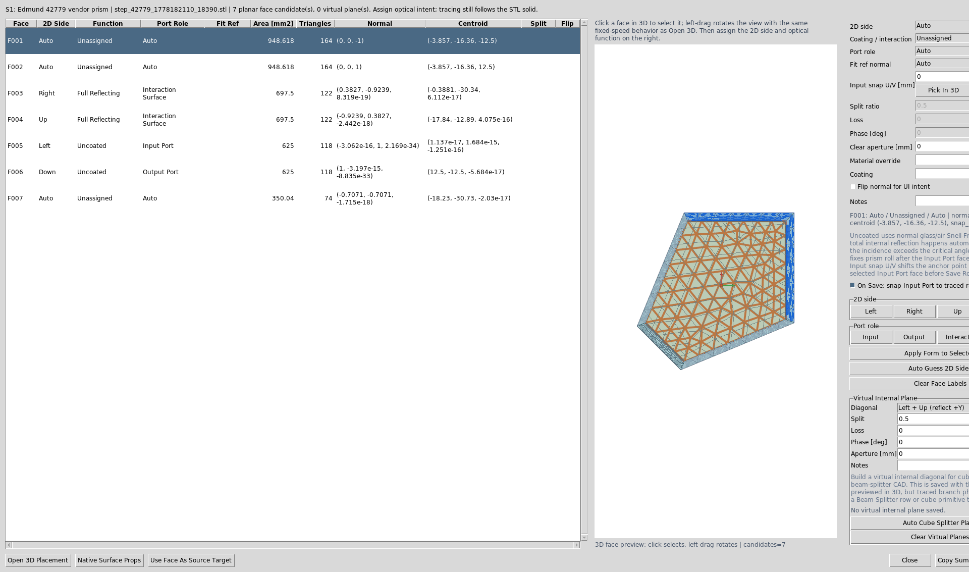
Assign Optical Face Roles
The face-assignment dialog appears automatically after import. You can reopen
it later from Actions -> Assign CAD/STL Optical Faces. The UI clusters
planar mesh triangles into candidate faces and gives them stable face IDs.
For this tutorial, the automated side labels are used as demo metadata:
Left  = Input,  function Transmit/Port
Right = Mirror, function Mirror
Up    = Mirror, function Mirror
Down  = Output, function Transmit/Port
Front/Back = Absorber/Mechanical
For each selected face, you may either use the quick buttons or set the
2D side and Function fields directly. Pressing Save Roles applies
the currently selected face form before saving, so Apply Form to Selected is
only needed when you want to commit a form edit and continue editing other
faces before the final save.
Face roles make the imported CAD usable in placement tools, inspection reports, and CAD-first ray tracing. They are not a substitute for checking the vendor drawing.
For Edmund 42779 specifically, the fold faces are vendor-coated reflective
faces, not uncoated faces. Use Full Reflecting when the drawing or product
page says the surface is aluminized or otherwise coated. Use Uncoated when
the face should follow normal glass/air Snell-Fresnel physics; total internal
reflection then happens automatically if the geometry and refractive index
really satisfy it.
Understand Side Labels, Axis Fits, And Optical Functions
The face-assignment dialog intentionally separates three ideas that are easy to mix together:
2D sideis an authoring and placement label.Left,Right,Up, andDownrefer to the face’s role in the projected 2D layout after the CAD solid is placed.FrontandBackrefer to the thickness faces along the out-of-sliceXdirection.Fit referenceis a physical 3D world-axis target for a selected face normal.-Z normalmeans “rotate this CAD face so its outward normal points toward world-Z.”-Y normalmeans the normal points downward in the YZ layout view.Functionis the optical law.Mirrorreflects.Transmit/Portlets the material boundary behave like a port and can anchor downstream rows.Uncoatedmeans use the glass/air Snell-Fresnel physics, including total internal reflection when the incidence angle is above critical.Absorberstops the ray.
In the YZ plot, +Z is to the right and +Y is upward. +X and -X
are front/back, out of the screen. A face can therefore be side_2d = Left
while using fit_reference = -Z normal; those are not contradictory. The
first is the projected port name, and the second is the 3D normal direction
used by the pose solver.

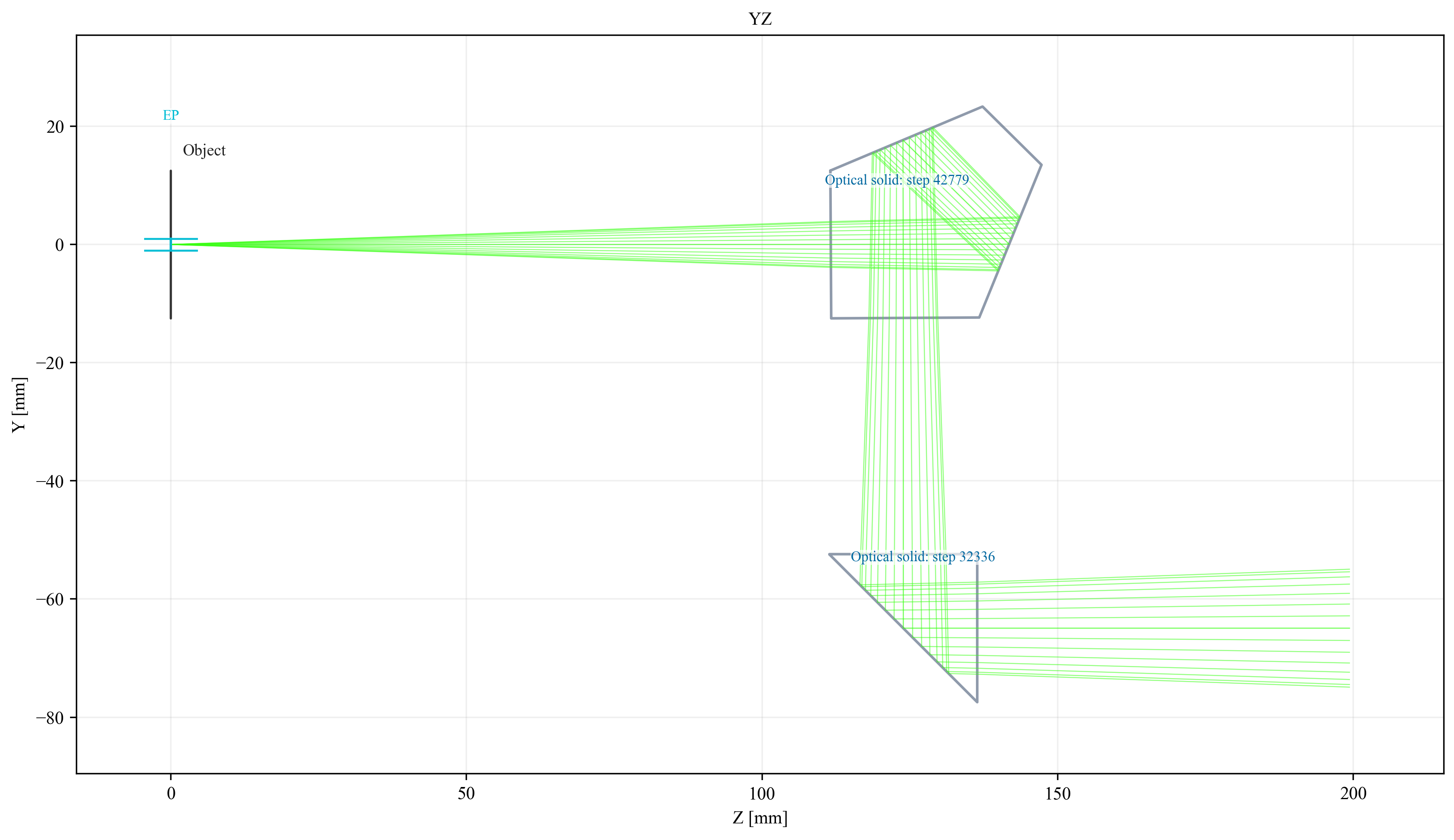
The examples match the attachment/penta.py YZ cascade snapshot. Blue
segments are placement ports and red segments are coated penta-prism fold
faces; both are drawn with equal length where they represent equal
legs/folds. The amber right-angle-prism hypotenuse is Uncoated and
reflects by total internal reflection when the incidence angle supports it.
Gray arrows show world-axis normal fit references.
Examples From penta.py
The generated 2D.png example has two different orientation cases:
The upper
42779penta prism receives the source fan from the left along+Zand sends the bundle downward along-Y.The lower
32336right-angle prism receives that downward-Ybundle and sends it back to the right along+Z.
For the 42779 penta-prism orientation used by penta.py, the practical
face mapping is:
Face |
Authoring role |
Fit reference |
Expected behavior |
|---|---|---|---|
|
|
|
Rays enter from the left side of the YZ drawing while travelling
roughly along |
|
|
usually |
First internal fold. Do not label this face |
|
|
usually |
Second internal fold. It is another reflective law surface, not the downstream placement port. |
|
|
|
Rays leave the prism downward. The next row is placed from this port when it is the selected output. |
|
|
|
These faces are out of the YZ slice and usually should not be the penta-prism optical path ports. |
|
|
usually |
Small non-path face; keep it unassigned unless the vendor drawing says otherwise. |
For the 32336 right-angle prism in the lower half of 2D.png, assign by
the visible YZ face geometry instead of assuming the same face ids as the
penta prism. CAD face ids depend on the vendor body and tessellation, but the
roles are stable:
Visible face |
Authoring role |
Fit reference |
Expected behavior |
|---|---|---|---|
Top horizontal leg |
|
|
Receives the downward |
Slanted hypotenuse |
|
usually |
The bare glass-air face folds the ray toward |
Right vertical leg |
|
|
Rays leave to the right along |
Front/back thickness faces |
|
|
These faces are out of the YZ slice and should not be selected as the prism path ports for the shown cascade. |
The ambiguous slanted surfaces should normally be assigned by optical law, not
by where the beam goes after several interactions. In the penta prism, the
slanted folded faces are coated Mirror faces. In the right-angle prism
shown by penta.py, the slanted hypotenuse is Uncoated; TIR is a result
of the incidence angle and media state, not a face label the user should have
to fake. Down and Right belong to the port faces that the ray actually
exits through. Assigning a port side to a slanted fold face may still let the
ray reflect when its Function is reflective, but it gives placement/path
tools the wrong semantic hint.
The combinations below show the most common outcomes:
Face-role combination |
What to expect |
Typical mistake it avoids |
|---|---|---|
|
The incoming |
Treating the final beam direction as the label for every slanted face. |
|
The incoming |
Reusing the penta-prism |
Same input and mirror faces, but |
The physical ray still follows Snell/reflection laws, but downstream row placement is biased toward a right-side port convention. |
Accidentally placing the next prism to the right when the physical cascade should continue downward. |
|
The input face is fit with the opposite normal. The CAD body can appear flipped relative to the incoming axial ray. |
Confusing a ray direction |
|
Reflection can still occur, but reports and placement helpers may name the mirror as the downstream output side. |
Using side labels as physics instead of using |
|
The path couples through the prism thickness direction, often out of the YZ slice. |
Mistaking front/back CAD thickness faces for the 2D left/right optical faces. |
Orient From The Input Face
The face-role dialog can solve one useful first pose directly when you press
Save Roles. Keep On Save: snap Input Port to traced ray enabled.
In this tutorial the entrance face is labeled Left and marked as
Input Port. If a traced ray/path already exists, Save Roles snaps that face
to the current Path view or the outgoing traced segment after the previous table
surface and aligns its outward normal against the incoming ray. If no traced ray
is available yet, it falls back to the standard axial convention: outward normal
-Z and incoming layout ray +Z.
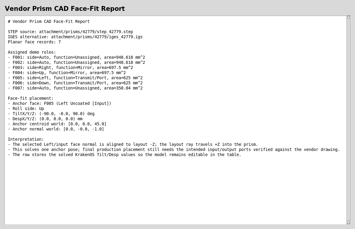
The report records the selected face, solved TiltX/Y/Z values, solved
DespX/Y/Z values, and the world-space normal after placement.
The solved values are normal KrakenOS table fields. After the first fit, the user can continue editing the row manually, move the element as a grouped component, or add sequential/non-sequential components before and after it.
Off-Center Entrance Points
Some vendor prism sketches show the incoming ray hitting the entrance face away
from that face’s geometric center. The CAD/STL face dialog now exposes
Input snap U/V [mm] on each face. When the selected face acts as
Input Port, Save Roles aligns that offset anchor point to the traced
incoming ray instead of always using the face centroid.
U is a deterministic in-plane axis that prefers the face-plane projection
of local +Z when available; V is the orthogonal in-plane axis. In the
common YZ layout view this means a bottom or top face usually uses U for
left/right movement along the sketch. For an off-center entrance, adjust
Input snap U/V [mm] first; use Pick In 3D to click the exact entrance
point on the previewed face when the vendor drawing already gives that hit
location. Use row DespY/Z only for later whole-solid placement changes.
Read The Fitted Layout
After applying the face-fit pose, the 2D layout shows the prism as a traced optical solid with its updated placement.
This snapshot is generated by attachment/penta.py. The first imported
prism is the 42779 penta prism; the second imported prism is the
32336 right-angle prism. This is the point where the design can
continue like any other KrakenOS UI table row: edit material, thickness,
pose, source settings, detector settings, and analysis mode.
For an optical CAD/STL solid with only an Input Port anchor, the UI now
uses the traced physical exit to place the next row. Add an explicit
Output Port only when you want to override that physics-derived exit and
force a particular downstream face to become the placement reference. When an
explicit Transmit/Port output face is present, the solid row Thickness
becomes the downstream standoff from that output port to the next row. In this
penta-prism workflow the row after the prism is the
Image detector plane, so increasing the prism-row Thickness moves the
detector farther along the outgoing output-port direction instead of along the
original axial +Z station. This is why a bottom-output prism places the
Image plane below the prism after the face roles are saved.
Chain Another Prism After A Folded Path
A second imported prism can be placed after a folded prism path without manual
global Tilt/Desp trial and error. The row order is still the optical
sequence:
Object -> first CAD prism -> lens/doublet rows -> second CAD prism -> Image
For the second CAD prism:
Import or convert the vendor STEP/IGES/STL body.
Set the optical material in the table
Glasscolumn. For example,Glass = BK7means the whole closed CAD solid is traced as BK7. Per-facematerialnotes in the face-role dialog are currently documentation, not the authoritative ray-trace glass.In
Assign CAD/STL Optical Faces, label the entrance faceLeftwithFunction = Transmit/Port. The UI uses theLeftside as the input anchor convention.Label the outgoing face
Transmit/Portwith a non-left side such asRight,Up, orDown. That face defines where downstream rows are anchored.Label a coated fold face
Full Reflectingwhen the drawing says it is aluminized or mirrored. UseUncoatedfor a bare internal fold face; the actual trace then produces total internal reflection automatically when the glass index and incidence angle satisfy it.Click
Save Rolesand thenUpdate.
When a CAD/STL row follows an existing output port, the UI now aligns its
Left face to the active optical path instead of leaving it at raw global
table coordinates. The following row is then placed from that second prism’s
selected output face. This is the intended “align to optical axis” workflow:
face labels define the local prism ports, the table order defines which path is
active, and Update solves the placement.
Roll Reference Faces
An entrance face alone is not enough to orient an arbitrary prism. Aligning the
Input Port face fixes the incoming ray direction, but the solid can still
roll around that ray. Use Fit ref normal on one nonparallel face to remove
that ambiguity.
For example, after assigning the ray entrance face as Input Port, select a
second face whose outward normal should point upward in the layout and set:
Fit ref normal = +Y normal
To flip the same prism about the layout Y convention, change that reference to
-Y normal or choose the opposite physical face and keep +Y normal. The
same rule works for +Z normal/-Z normal or +X normal/-X normal
when the reference face is not parallel to the entrance normal. If the selected
reference direction is parallel to the input normal, it cannot define roll; pick
a different nonparallel face.
This is stricter than using only 2D side labels. The side labels still
document the YZ plot and path ports, while Fit ref normal tells Save
Roles how to orient the solid in 3D.
Single-Face Fold Mirrors
For a right-angle mirror or mirrored prism used only as an external fold, do
not assign an Input Port. Select the slanted reflective face and set:
2D side = Left
Function = Mirror
Port role = Interaction Surface
Then assign the desired outgoing leg face as Function = Transmit/Port and
Port role = Output Port. Use Down for a downward fold, Up for an
upward fold, or Right for a forward output. Save Roles places the
slanted mirror face on the incoming path and solves the CAD pose so the
reflected ray follows that output side. In this workflow Left means “the
incoming fold face for the active path”; it does not mean the face must appear
vertical in the 2D drawing.
For a physical prism where the ray enters glass, reflects internally, and exits
glass, use the normal prism workflow instead: entrance Transmit/Port as
Input Port, exit Transmit/Port as Output Port, and internal coated
or uncoated fold faces as Interaction Surface.
Run The Validators
Use these checks after changing CAD import, face clustering, or face-placement code:
python -m KrakenOS.UI.validate_vendor_prism_42779
python -m KrakenOS.UI.validate_optical_solid_chained_ports
python -m KrakenOS.UI.validate_optical_cad_solid_import
python -m KrakenOS.UI.validate_optical_solid_face_fit
python -m KrakenOS.UI.validate_optical_solid_path_fit
validate_vendor_prism_42779 proves that the bundled STEP file resolves to a
cached STL, the mesh is trace-ready, the scale is plausible, the face clusterer
finds usable optical candidates, and the face-fit solver can align the selected
input face to the incoming -Z normal convention.
validate_optical_solid_chained_ports isolates the placement rule: ordinary
follower rows and a second CAD/STL optical solid both inherit the active output
port frame, and the final image plane is anchored to the second optical solid’s
output port.
What This Proves
This case study exercises the CAD-first side of the UI without overstating the current physics:
real vendor STEP import through the CAD conversion service;
versioned vendor source assets beside the optical project;
closed-solid diagnostics before ray-trace trust;
planar face clustering on a converted vendor mesh;
optical port/fold/mechanical face metadata;
face-normal placement into KrakenOS
TiltandDesptable fields;separation between CAD authoring metadata and physical tracing assumptions.
Common Mistakes
I imported the CAD file, so the UI should know the optical faces.Mechanical CAD usually does not encode optical intent. The UI can cluster planar faces, but the user must verify which face is input, output, fold, coated, unused, or mechanical.
The face labels look correct, so the trace must be correct.Face labels are metadata, but selected optical functions now affect the imported STL interaction where implemented:
Mirrorforces a reflective STL face hit, andTransmit/Portidentifies the output port used to place following rows. The trace still follows the mesh, row material, and row pose. Confirm the material and placement against the drawing.I set material inside the face-role dialog, but the prism index did not change.Set the prism glass in the main editable table
Glasscolumn on the CAD/STL optical-solid row. That row material is what the KrakenOS non-sequential trace uses for the closed solid.I changed Image thickness and the detector did not move.For optical-solid output-port workflows, edit the CAD/STL solid row
Thicknessto change the distance from the output face to the following row. The finalImagerow thickness is normally0.The STEP file is enough for production.Keep the drawing and curve documents with the project. They are needed to verify dimensions, glass assumptions, coating notes, and vendor-specific surface intent.
The cached STL path is the source of truth.Treat the STEP or IGES file as the source of truth. The STL is generated cache output and can be recreated.