Case Study 16: 3D Hardware Alignment Workflows
Goal
This case study is a click-by-click tour of the embedded 3D tools that support real hardware alignment. It complements the vendor-prism CAD case study by focusing on the 3D controls themselves:
open the embedded 3D inspector and read the optical-axis/face overlays;
use the
CAD/STL placement handlerinstead of a dense second toolbar;understand what each placement action changes in the table;
arm a 3D pick workflow and read the active-mode badge;
carry an imported STEP overlay with free Open 3D movement;
use
Snap STEP Normal->Optical Axisto align a picked STEP face normal to a straight or bent traced optical axis;use in-scene
STEP rotation handlesfor repeated vendor-hardware rotations;know when to use
Done 2DorClosefrom the 3D view.
The screenshots in this tutorial are generated from the live Tk/VTK UI with:
python -m KrakenOS.UI.capture_3d_hardware_alignment_case_study_screenshots
The lightweight validator checks that the case-study page, screenshots, and UI contracts are still present:
python -m KrakenOS.UI.validate_3d_hardware_alignment_case_study
Open The 3D Inspector
Start from the fitted vendor prism layout used in
Case Study 14: Vendor Prism CAD Import And Face Placement. Select the CAD/STL prism row and choose
Open 3D.
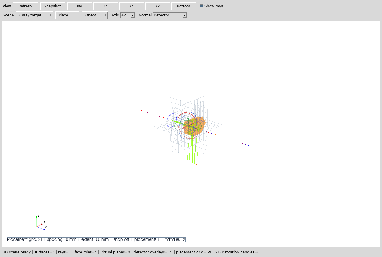
The long blue dotted line is the layout optical axis. When an axis is chosen for placement it is drawn again as a solid highlighted line, so the selected path remains visible even when rays are hidden. The coloured face markers are the assigned CAD/STL optical-face roles. Plain left-click selects surfaces, rays, or imported hardware. Left hold-drag rotates the camera around the current view center.
The embedded 3D inspector opens in a clean physical-scene mode. The Refs
checkbox adds row-sized Object/Image reference disks, Det adds detector
active-footprint outlines, Miss adds detector-miss crosshairs, and
Placement handles adds row-backed pose handles. These diagnostics are
independent so a blue reference disk, orange detector aperture, red miss marker,
or placement handle cannot be mistaken for a ray-law interaction unless the
user explicitly enables that overlay. The top Done 2D button and the top
Close button both refresh the 2D plot when 3D placement, STEP promotion, or
direct right-click face assignment has changed row metadata.
Use The CAD/STL Placement Handler
Choose Actions -> 3D Place/Orient Selected CAD/STL Solid when row pose needs
to be edited. Plain left-click on a CAD/STL solid only selects it; this keeps
face-function assignment and ray/axis inspection from unexpectedly opening
placement controls. The explicit placement command opens a contextual right-side
panel instead of a floating popup or a permanent second toolbar row. This keeps
the controls visible when the main UI is tiled or fullscreen, and it avoids
covering the 3D scene.
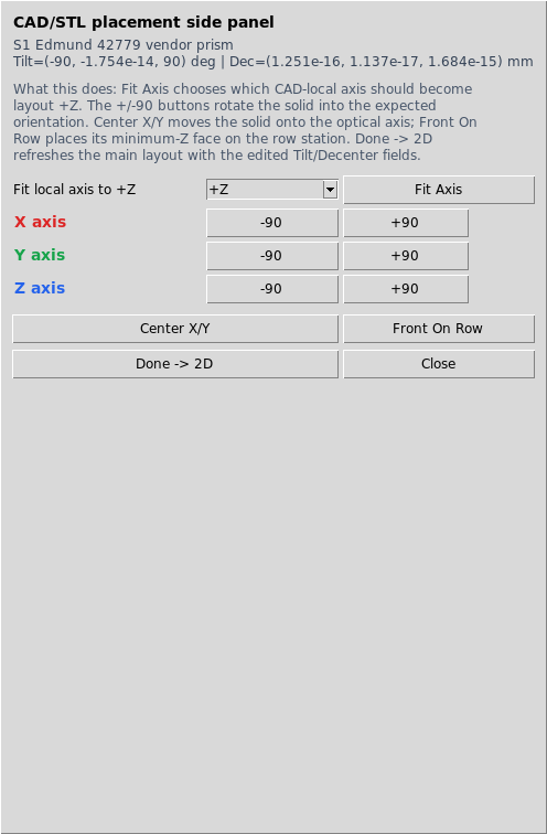
The help text is intentionally visible in the side panel:
Fit Axischooses which CAD-local axis should become layout+Z.X/Y/Z +/-90rotates the solid and updates the rowTiltfields.Center X/Ymoves the solid onto the optical axis.Front On Rowplaces the minimum-Z face on the selected row station.Done -> 2Drefreshes the main 2D layout from the edited row pose.
Practical rule: first use Fit Axis for the gross CAD coordinate convention,
then use X/Y/Z +/-90 for orientation, then use Center X/Y and
Front On Row for placement. The side-panel Close button only hides the
panel; the top-level Done 2D or top-level Close button refreshes the
visible 2D layout when the 3D view has pending row metadata changes.
Read Active-Mode Badges
Some 3D workflows need a second click. Those workflows now show a badge inside the VTK scene so the user knows what the next click will do.
Center STEP Axis is armed here. The next click should be either a
planar/circular feature on an imported STEP body or, if a STEP component is
selected, a KrakenOS surface whose axis should be used as the target.
The same badge mechanism is used by Obj->LED, Center Row->Optical
Axis, and Source Target.
Rotate Imported STEP Hardware
Clicking an imported lens, optical, LED, or camera STEP overlay selects that
component and draws coloured X/Y/Z rotation handles around it inside the 3D
scene.
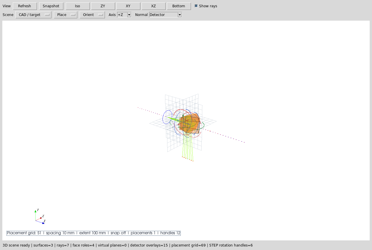
Hovering a red, green, or blue end arrow highlights that rotation command
before it is clicked. There is one half-arc per axis, with opposed arrows at
the two ends. The two end arrows are separate commands: one applies
X/Y/Z +90 and the other applies X/Y/Z -90. Click the highlighted
arrow while watching the imported STEP overlay rotate immediately around its
own component center in the same 3D scene.
The Carry-row Rotation handles checkbox hides or shows these arcs when
face picking needs an unobstructed view. This replaces the older floating
popup and duplicate toolbar menu, so rotation is tied to the selected STEP
component and does not cover the geometry.
Carry Imported STEP Freely
Open 3D can import arbitrary optical STEP, lens STEP, camera STEP, or LED STEP
hardware directly from CAD / target -> Import STEP. The arbitrary optical
STEP command uses a separate optical overlay slot, so importing an optical
element into a preset with an existing lens STEP does not replace the lens
overlay. A newly imported optical STEP is selected and carried by the cursor
immediately until the next click drops it. If the file dialog closes while the
pointer is outside the VTK canvas, the first in-canvas pointer motion attaches
the STEP center to the cursor plane. Use CAD / target -> Arm Selected STEP
Carry when an already-imported component should show carry status before it
is moved again.
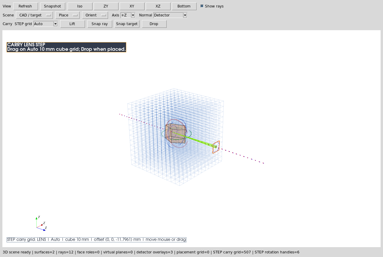
STEP carry uses free movement only. A newly imported optical STEP follows the
cursor immediately and drops on the next click; when the file dialog leaves
the pointer outside the VTK canvas, the first in-canvas pointer motion
attaches the STEP center to the cursor plane. To carry an already-imported
STEP overlay, hold the pointer on the STEP body briefly, or start
dragging on the body, until the carry anchor snaps to the STEP center and
an in-scene grip cursor appears there. Release to drop/commit the placement.
The OS pointer is not warped during this hold-drag gesture; synthetic Tk/VTK pointer
motion can feed back into the drag loop and make the component jump. The
carry path projects the cursor ray onto a drag plane through the STEP center
and moves continuously on that plane. Ctrl+drag keeps the same left-drag
gesture available for camera rotation, and Esc cancels the active
carry/pick operation. The selected overlay keeps its optional rotation
handles, so the normal workflow is: import, hold-drag the hardware near the
traced ray bundle, click the STEP surface whose normal should define the
optical entrance/exit direction, and then click the intended blue
Optical Axis N overlay. During the second click mode, only optical-axis overlays are
accepted; the overlays are generated from traced path branches and remain
pickable even when regular rays are hidden. After the snap, the selected
optical axis remains highlighted as a solid line so the chosen path is
visible even when Ray Off is active. The picked face center moves onto
the clicked optical path point, and the picked normal rotates parallel to
that local path direction. Click the coloured handles to flip the sign if needed before
assigning face functions. A right-click on a row-backed optical CAD/STL face
previews the picked face and assigns Uncoated, Full Reflecting,
splitter, absorber, or unassigned physics directly on that face. This
right-click Open 3D workflow writes OpticalSolidFaces immediately and
does not wait for the older face-role dialog’s Save Roles button. In
this direct workflow, Uncoated and Full Reflecting are physical
interaction surfaces, not inferred output ports; they do not re-anchor the
downstream Image row. Explicit input/output ports still belong to the
full face-role editor when a prescription-style port chain is intended. New
promoted optical STEP rows default detected faces to Uncoated interaction
surfaces, so a bare glass-air boundary does not need a manual assignment
before it can refract or TIR.
A Full Reflecting face on a closed optical solid is treated as external
only before the ray enters that volume. After entry, the mirror hit keeps
the ray inside the same solid so the next physical mirror or exit face can
be found by the non-sequential chooser.
Hovering a row-backed face shows a small badge with its current function and
port role. Manually assigned faces remain visible as non-pickable colored
surface tints in Open 3D so a previously authored face can be recognized
before the next surface is picked, without converting the body into a
persistent mesh-outline display. Open 3D scene surface actors are drawn
double-sided and row-backed CAD/STL solids get stronger edge/body retention
styling plus a final wireframe retention pass while rays are on, so a
ray-off/ray-on refresh should not make CAD/STEP-derived bodies disappear
because of vendor mesh winding or dense ray overlays. Escaped or missed ray
display segments are also capped to the current Open 3D scene envelope before
VTK camera bounds are recomputed. This is only a viewer safeguard: the traced
ray path, ray-event metadata, raykeeper arrays, and CSV export keep the
original physical coordinates and terminal status. The old cube/grid plane
overlay is suppressed during this workflow; placement metadata still drives
the handles and status text, but the three grid planes no longer obscure the
picked faces.
When an Open 3D assignment behaves unexpectedly, copy the main-window Debug
panel or read ~/.cache/krakenos/logs/kraken_debug_latest.log. Lines that
start with Open3DTrace show the exact interaction sequence: the
right-click actor, picked row or STEP overlay, matched face id, selected face
function, metadata save, ray visibility toggle, scene-refresh mesh rows, and
actor counts after refresh. This is the preferred evidence for debugging a
disappearing-body report because it records what the UI picked, not only what
the screenshot shows afterward.
This is a hardware-overlay workflow. It places real vendor CAD in the same 3D
scene as rays and optical objects. Use
CAD / target -> Promote STEP to Optical Solid Row when the positioned
overlay should become a traced file-backed optical solid row. The promotion
writes a cached, locally centered STL from the current Open 3D placement,
stores the original STEP path and overlay rotation/offset metadata on the row,
and opens the CAD/STL face-role editor so the material and optical functions
can be reviewed before tracing. Use File -> Import Optical CAD/STL Solid...
when the STEP/STL geometry should be inserted directly without first placing it
as an Open 3D hardware overlay.
Pick Source Targets From 3D
The 3D inspector can also arm Source Target selection. This is useful for
multi-source, source/object split, and beam-splitter workflows where a source
must aim at a CAD/STL face or surface row.
When this badge is visible, the next click should be a surface or CAD/STL solid row. If the row has assigned optical-face metadata and the click lands near one of those faces, the Scene Source Manager can use that face anchor.
What This Proves
This case study exercises the user-facing 3D workflow rather than the optical physics of one particular component:
embedded VTK/Tk 3D inspector launch and refresh;
optical-axis guide in the 3D scene;
CAD/STL optical-face role markers;
contextual CAD/STL placement side panel with inline help;
table-backed row pose edits through
TiltandDespfields;active-mode badges for multi-click 3D workflows;
imported STEP carry placement with free movement;
imported STEP
Snap STEP Normal->Optical Axisplacement;direct picked-face optical function assignment with persistent non-physical assigned-face outlines and immediate metadata save;
structured
Open3DTracediagnostics for click, assignment, and refresh reconstruction;promotion from positioned STEP overlay to a file-backed optical solid row;
selected STEP rotation handles for imported hardware overlays;
source-target picking from the 3D view.
Common Mistakes
I closed the placement panel but the 2D plot did not change.Closing the placement panel only hides the handler. Use top-level
Done 2Dor close the 3D view when you want the 2D layout refreshed from the edited row pose, STEP promotion, or direct face assignment.Fit Axis and X/Y/Z rotation look similar.Fit Axismaps the CAD model’s local coordinate convention onto layout+Z. The rotation buttons are subsequent explicit 90-degree orientation edits.The active badge is just a status message.Treat it as a modal instruction. While the badge is visible, the next click is consumed by that workflow rather than by normal row/ray selection.
The STEP rotation handles rotate CAD/STL optical solid rows.They rotate imported lens/optical/LED/camera STEP overlays. File-backed optical CAD/STL rows use the separate
CAD/STL placement handler.I carried a STEP component but the ray trace did not change.Open 3D STEP carry moves lens/optical/camera/LED hardware overlays. It is for mechanical context and placement planning until you run
CAD / target -> Promote STEP to Optical Solid Row. Ray-traced CAD/STL optics must be optical solid rows so the kernel receives real surface geometry and face-role metadata.I assigned every CAD/STL face and then the 3D scene disappeared.That should not happen. Open 3D keeps the previous valid scene if a trace rebuild produces no surface meshes or suspiciously drops previously visible file-backed surfaces, draws surface actors double-sided, and the validator covers the path where a promoted optical solid has all of its exposed faces assigned before the scene refreshes. The direct Open 3D right-click face menu applies immediately and stores direct
Uncoatedpicks as interaction surfaces; the olderSave Rolesbutton only belongs to the full face-role editor dialog.