Case Study 12: Optical STL Prism And Face Roles
Goal
This case study shows the arbitrary optical-solid workflow:
load a closed STL prism as a KrakenOS
Solid_3d_stloptical row;trace through the row material instead of treating the mesh as decoration;
inspect the mesh before trusting it;
assign side labels and optical functions to imported CAD/STL faces;
verify that traced STL hits map back to the assigned face metadata.
The screenshots in this tutorial are generated from the live Tk UI with:
python -m KrakenOS.UI.capture_optical_stl_prism_case_study_screenshots
Load The Optical STL Prism
Start the UI with
python -m KrakenOS.UI.layout_editor.Choose
Examples -> Non-Sequential / Advanced Surfaces -> Examp_Phase6_Optical_STL_Prism.Keep
Trace mode = Non-Sequential Preview.Click
Update.
The optical row is S1 Phase 6 STL prism. It stores the native KrakenOS core
attribute:
Solid_3d_stl = KrakenOS/Examples/prism.stl
Glass        = BK7
The STL file is not just drawn in the viewer. KrakenOS traces the ray through the closed mesh using the row material, row pose, and row distance settings.
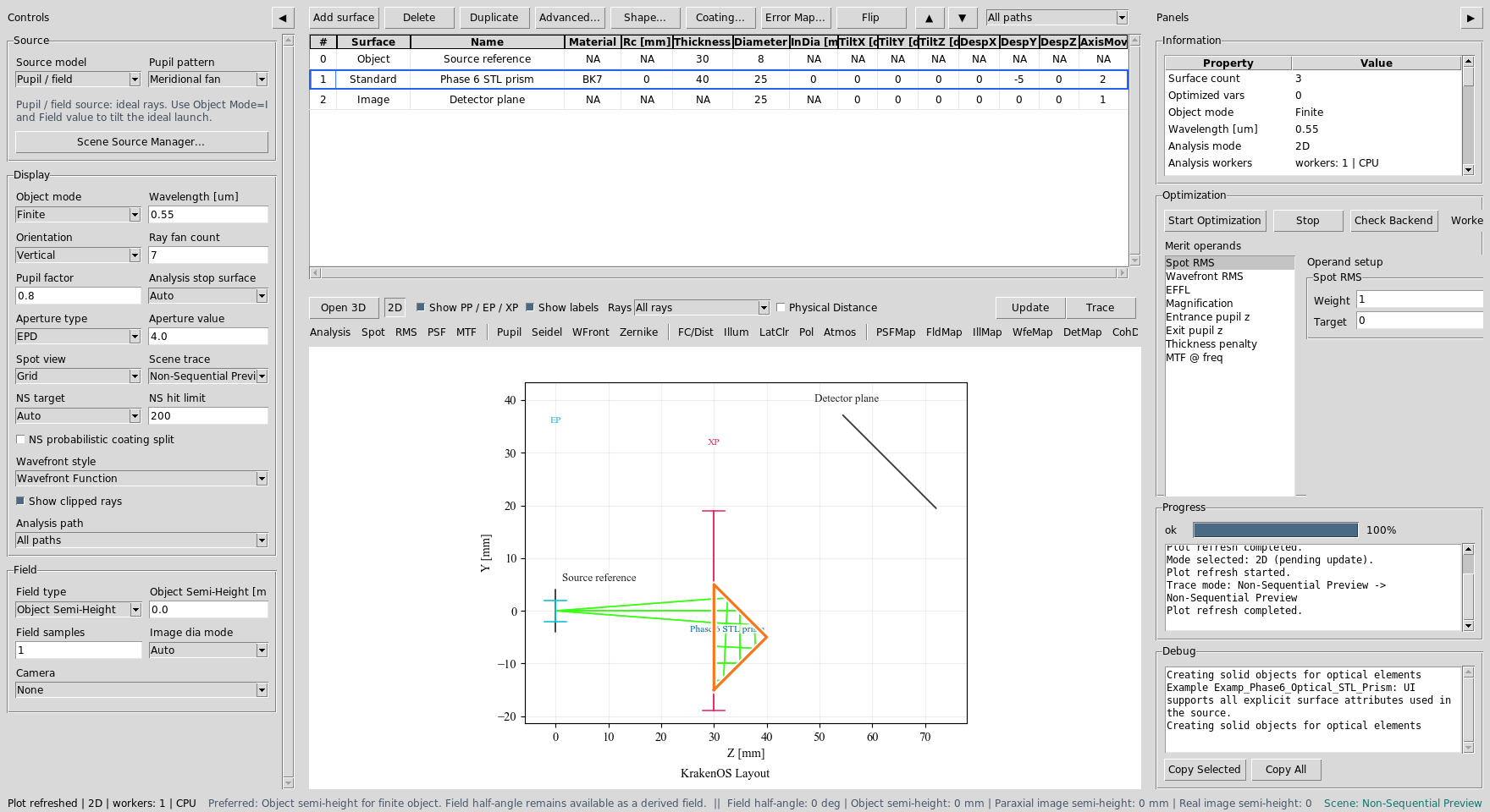
The table contains a file-backed STL prism row between the source reference and detector plane.
The Source panel opens Scene Source Manager... for geometric launch-bundle
details. For random geometric sources, Cone half-angle [deg] in the manager
sets the ray divergence half-angle. For Gaussian laser sources, switch to
Source model -> Gaussian beam in the Source panel and use
GB input mode -> Diameter + divergence; the GB full div [mrad] field is
the full-angle far-field divergence normally quoted on laser datasheets.
Read The 2D Trace
With Non-Sequential Preview active, the plot shows the ray bundle entering
the STL prism and interacting with the closed mesh. In this stress-pose example
the chief ray has several STL hits; not every displayed ray needs to reach the
detector before the hit-sequence diagnostics are useful.

The projected solid footprint comes from the STL mesh. The ray path comes from KrakenOS non-sequential tracing, not from a decorative overlay.
Assign Optical Faces
Select row S1 Phase 6 STL prism and choose
Actions -> Assign CAD/STL Optical Faces.
For this demo, use these labels:
Left  = Input,  function Uncoated
Right = Output, function Uncoated
Down  = Interaction Surface, function Uncoated
Front/back mechanical faces can be marked Absorber/Mechanical when they
are not intended optical ports.
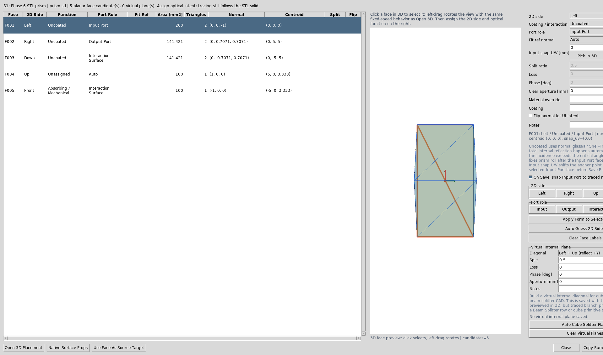
The dialog clusters planar STL triangles into selectable face candidates. Side labels make the same imported solid usable in placement, 3D inspection, and hit-sequence diagnostics.
Face roles are metadata. They document optical intent and support placement and
diagnostic tools. Full Reflecting faces now force reflective STL hits in
non-sequential tracing, while total internal reflection remains a physical
Snell-law outcome that only occurs when the incidence angle is above critical.
For uncoated prisms,
the physical trace still follows the closed STL geometry, material, and pose.
Uncoated output faces also define where rows after the optical solid
are anchored. The optical-solid row Thickness is the standoff distance from
the selected output port to the next row, such as an Image detector plane.
Inspect Mesh Readiness
Before trusting arbitrary vendor geometry, choose
Actions -> Inspect Optical CAD/STL Solids.
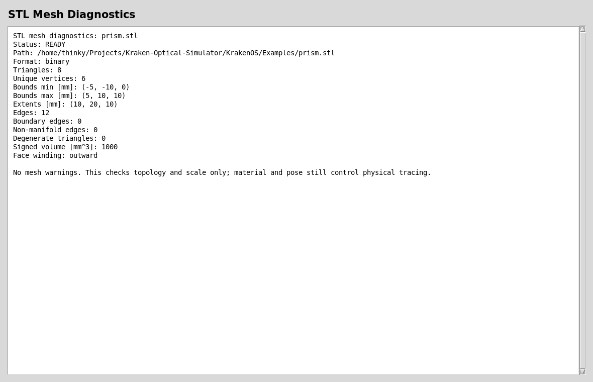
A trace-ready optical mesh should have finite scale, no open boundary edges, no non-manifold edges, no degenerate triangles, and usable winding.
Verify The Trace Sequence
The generated report below uses the same core prism example, traces one chief ray, then maps each STL hit back to the saved face-role metadata.
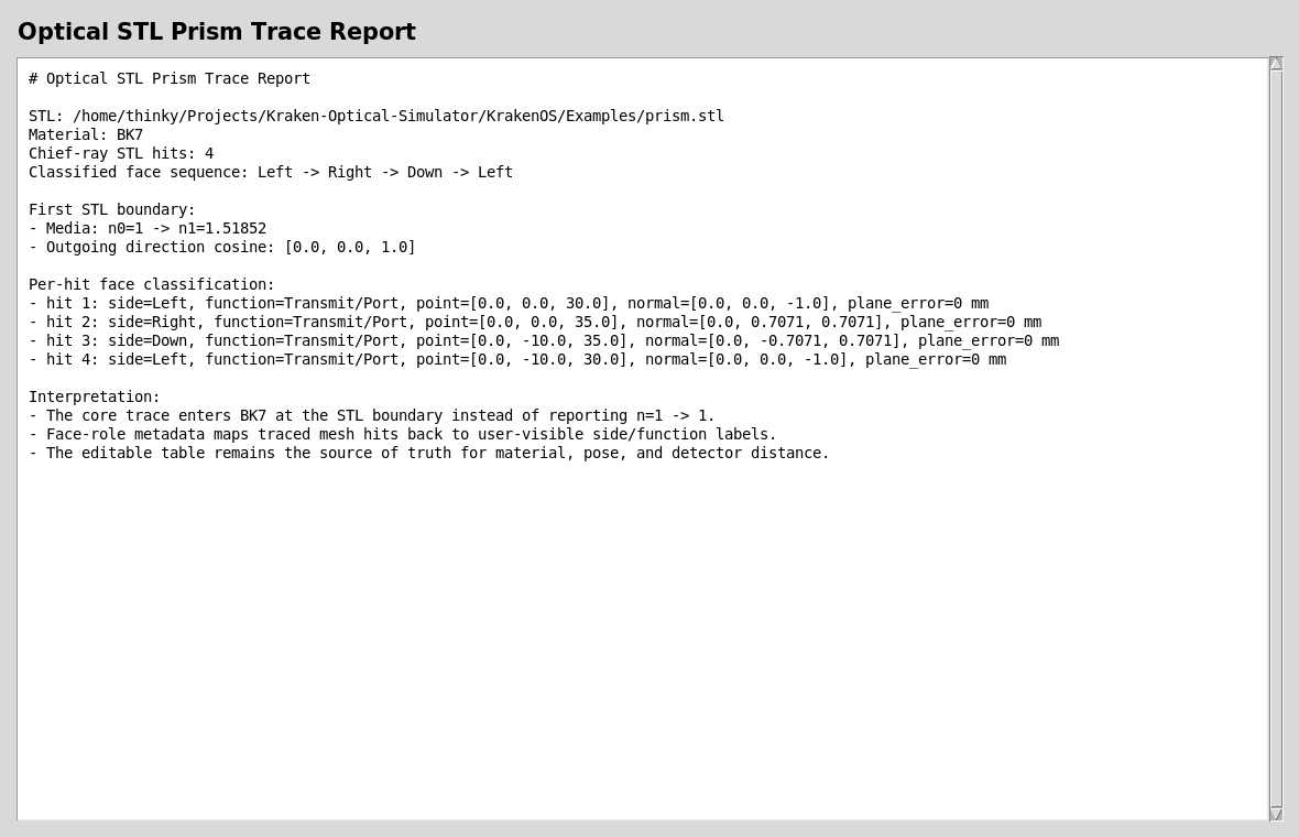
The important physics check is the first STL boundary:
n0=1 -> n1~=1.518 at 0.55 um for BK7. The classified face sequence
should read Left -> Right -> Down -> Left for this bundled prism pose.
Run The Python Examples And Validators
The direct KrakenOS core example is:
python KrakenOS/Examples/Examp_Phase6_Optical_STL_Prism.py
The regression checks behind this case study are:
python -m KrakenOS.UI.validate_stl_prism_media
python -m KrakenOS.UI.validate_optical_solid_face_roles
python -m KrakenOS.UI.validate_optical_solid_hit_sequence
Use these after changing STL import, non-sequential tracing, face-role assignment, or CAD/STL placement code.
What This Proves
This case study exercises several KrakenOS core and UI capabilities:
native
Solid_3d_stloptical-solid tracing;file-backed STL mesh display in the UI;
BK7 material transition at the first mesh boundary;
non-sequential ray paths through an arbitrary closed solid;
planar face clustering for imported STL/CAD geometry;
side labels and optical function metadata;
face-hit sequence classification for ray/debug reports.
Common Mistakes
I imported a mesh but rays pass straight through.Check that the row has
Glass = BK7or another real material, notAIR. Also runvalidate_stl_prism_media; the first hit should not reportn=1 -> 1.I assigned face roles but the prism did not move.Face roles do not pose the solid. Use
Actions -> 3D Place/Orient Selected CAD/STL Solidor editTiltX/Y/ZandDespX/Y/Z. Face roles are used by placement helpers and diagnostics after the pose is solved.Rays leave the output face but the detector is still axial.Make sure the output face is labeled
Transmit/Portand pressSave Roles. The following row will be anchored to that output face, and the optical-solid rowThicknesscontrols the distance to that row.My vendor STEP cube beam splitter does not split rays.Mechanical CAD usually contains only the outer cube. It does not define the internal coating, split ratio, phase, or loss. Use the UI beam-splitter primitive for traced splitting today, or save a virtual internal plane as authoring metadata for future CAD-first cube workflows.
The mesh diagnostics report says CHECK.Fix the mesh first. Open boundaries, non-manifold edges, inverted winding, or wrong scale can make the optical result meaningless even when the table material is correct.