Case Study 9: Zemax LED Source To Diffuse Object Imaging
Goal
This case study demonstrates a more realistic source/object split than the specular proxy case:
load a vendor Zemax
.DATLED source;route the LED through a 45 degree beam splitter;
illuminate a true
Diffuse Objectsurface;use guided Lambertian scatter to return light through the splitter;
pass the return path through a simple BK7 imaging lens;
inspect source throughput and camera-plane irradiance.
The screenshots in this tutorial are generated from the live Tk UI with:
python -m KrakenOS.UI.capture_zemax_led_diffuse_case_study_screenshots
Load The Layout
Start the UI with
python -m KrakenOS.UI.layout_editor.Choose
Layouts -> Beam Splitters / Folds -> Zemax LED Beam-Splitter Imaging.Keep
Trace mode = Non-Sequential Preview.Keep
NS probabilistic coating splitoff.
The first table row is an Illumination Source scene row backed by the OSRAM
green Zemax rayfile:
attachment/LED/rayfile_LSG_T676_20200827_Zemax/rayfile_LSG_T676_green_100k_20200827_Zemax.DAT
The Object row is reference geometry only. The useful optical chain is:
LED source -> beam splitter -> diffuse object -> beam splitter return ->
BK7 imaging lens -> Image plane.
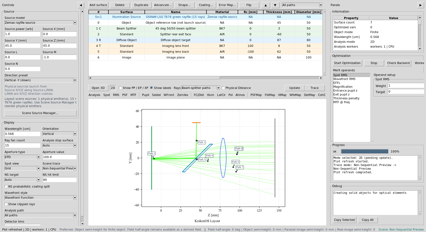
The layout combines a vendor rayfile source, beam splitter, diffuse object, imaging lens, and detector plane.
Read The Scatter Paths
Click Update. The 2D plot uses physical path labels plus scatter branch
rays. The diffuse object is the green vertical surface on the left. The blue
curves are the imaging lens surfaces on the return path.
The return rays are not mirror reflections from an Object Target proxy.
They are child branches spawned by the Diffuse Object row.
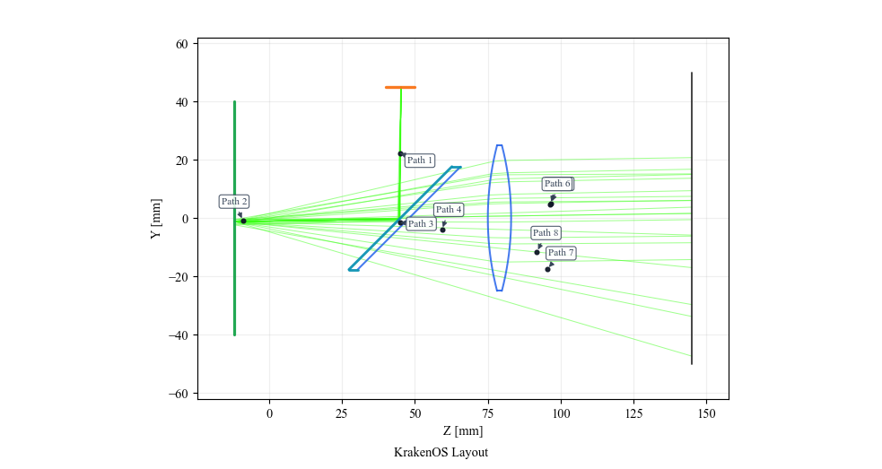
Use Path View
Open the table toolbar Path view dropdown and select:
Path 2: 45 deg 50/50 beam splitter to 45 deg 50/50 beam splitter via Diffuse object target
This isolates the source-to-object and object-return leg.
The Diffuse Object row is the physical scattering target.
Now select:
Path entry containing: 45 deg 50/50 beam splitter to Imaging lens back via Splitter rear exit face, Imaging lens front
This isolates one useful image path through the splitter exit face and lens.
The exact path number can change as deterministic diffuse child branches are
inserted before the imaging leg, so select the discovered path whose label
continues through Imaging lens front and Imaging lens back.

Path view remains useful even when the branch-code list is long.
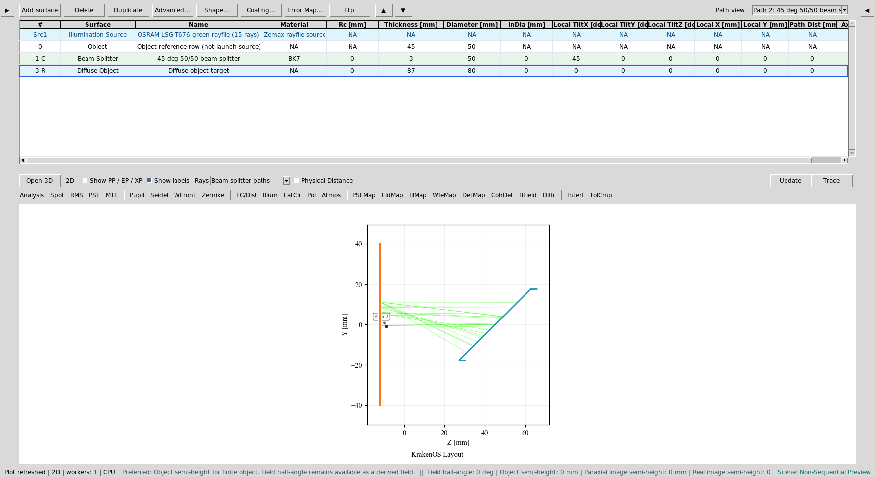
Inspect Diffuse / BRDF Settings
Right-click the Diffuse Object row and choose
Coating / Polarization -> Diffuse / BRDF Settings....
This preset uses the dependency-free built-in Lambertian model. Guided
target surface is set to the splitter return aperture so the deterministic
diffuse child rays can be traced through the useful camera branch.
Audit Source Illumination
Choose Actions -> Source Illumination Report. Set Target to:
3: Diffuse object target
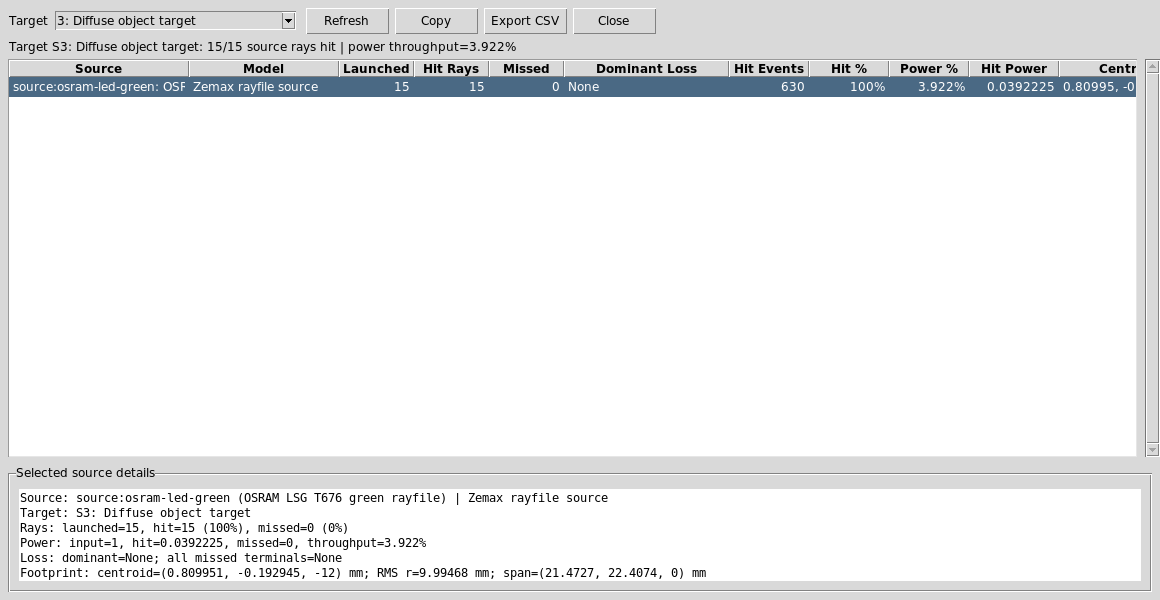
The report shows that the vendor LED source reaches the diffuse object and reports source throughput and footprint size at the target.
Now change Target to:
6: Image plane
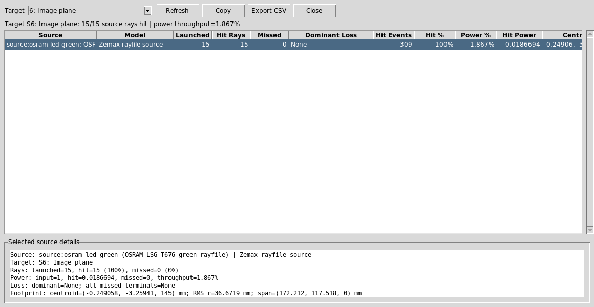
The Image-plane report verifies that source-driven diffuse return rays reach the detector after splitter and lens losses.
Run Image-Plane Analyses
Set:
Analysis path = All paths
Analysis surface = 6: Image plane
Detector bins = 64
Click DetMap and Update.
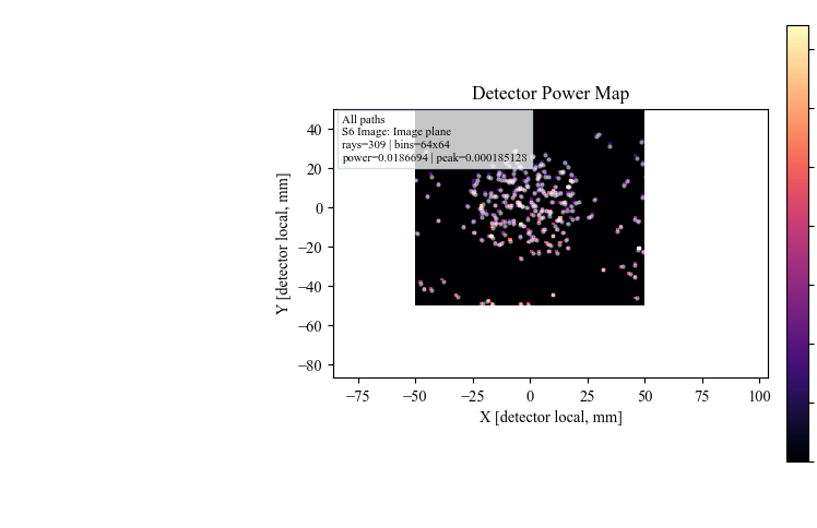
DetMap shows the Image-plane power distribution from the useful
source-to-diffuse-object return rays.
Click Illum and Update.
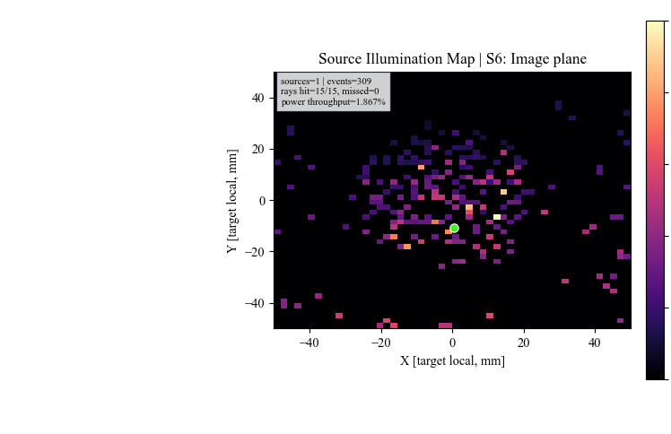
Illum uses the same source-hit records to show image-plane illumination
and centroid diagnostics.
Run The Python Example
The same layout has a scriptable example:
python KrakenOS/Examples/Examp_Zemax_LED_Beam_Splitter_Imaging.py
The script prints the rayfile source path and a per-ray trace summary, including whether each sampled LED ray hits the diffuse object and reaches the Image plane.
What This Proves
This case study combines several KrakenOS UI capabilities in one workflow:
vendor Zemax rayfile source import;
source/object separation;
deterministic beam-splitter branch spawning;
true
Diffuse Objectscattering instead of a specular proxy;guided Lambertian target sampling;
path filtering for a branch-heavy non-sequential scene;
detector power and source-illumination analysis at the Image plane.
Common Mistakes
I expected one clean return ray from the object.A diffuse surface creates many child rays. This is expected and is the point of replacing the specular proxy with
Diffuse Object.The Analysis path dropdown contains many Rscatter entries.Those are deterministic scatter branch codes. For the camera result in this tutorial, keep
Analysis path = All pathsand choose the Image plane as the analysis surface.The Source panel ray count did not change the explicit rayfile source row.This layout declares an explicit scene source in
SETTINGS["scene_sources"]. Edit the source row or Scene Source Manager when changing that source.I changed Guided target surface to None and fewer rays reached the camera.Unguided diffuse sampling sprays rays over the scatter cone. Guided target sampling keeps the UI preview deterministic while still weighting rays with the selected scatter model.