Case Study 5: Gaussian Laser Beam Expander
Goal
This case study demonstrates the laser workflow in the UI:
enter manufacturer-style laser data: beam diameter and full divergence;
let KrakenOS back-calculate the waist radius and waist location;
inspect the Gaussian
qpropagation report;convert a free-space laser line into a 3x Keplerian beam expander;
verify the before/after beam size and divergence;
run the
BFieldanalysis to show detector-plane field intensity and phase.
The screenshots in this tutorial are generated from the live Tk UI with:
python -m KrakenOS.UI.capture_gaussian_beam_expander_case_study_screenshots
Load The Laser Line
Start the UI with
python -m KrakenOS.UI.layout_editor.In the top menu choose
Layouts -> Sources / Illumination -> Gaussian Laser Beam Expander Case Study.Confirm the Source panel uses laser-datasheet input:
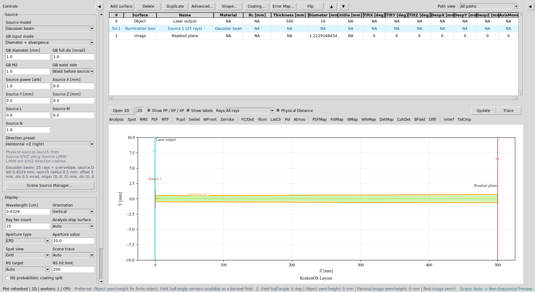
Source model       = Gaussian beam
GB input mode      = Diameter + divergence
GB diameter [mm]   = 1.0
GB full div [mrad] = 1.0
GB waist side      = Waist before source
GB M2              = 1.0
Wavelength [um]    = 0.6328
This means the laser output plane has a 1/e² beam diameter of 1.0 mm and a
full far-field divergence of 1.0 mrad. The UI hides or disables the
ordinary field/pupil inputs because the physical Gaussian source now defines
the illumination.
The Source panel is in Gaussian beam mode. Diameter and divergence are
the active input fields; object-field controls are not part of this source
workflow.
Click Update. The 2D layout shows the traced representative source rays and
the amber 1/e² Gaussian envelope.
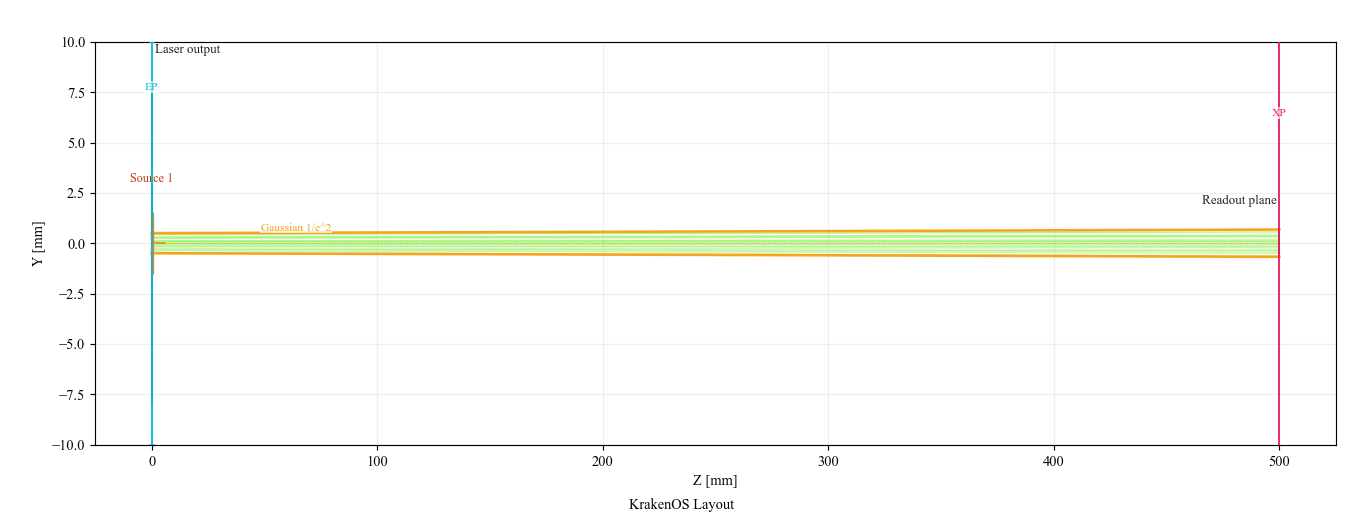
Free-space baseline: a 1 mm diameter, 1 mrad full-divergence laser propagates to the readout plane.
Back-Calculated Waist
Open Actions -> Gaussian Beam Report.
For this laser input, KrakenOS computes approximately:
waist radius w0       ~= 0.403 mm
waist location offset ~= 592 mm before the source plane
At the free-space readout plane, the beam is larger but the divergence is still the original datasheet value:
final 1/e^2 diameter ~= 1.36 mm
final half divergence ~= 0.50 mrad
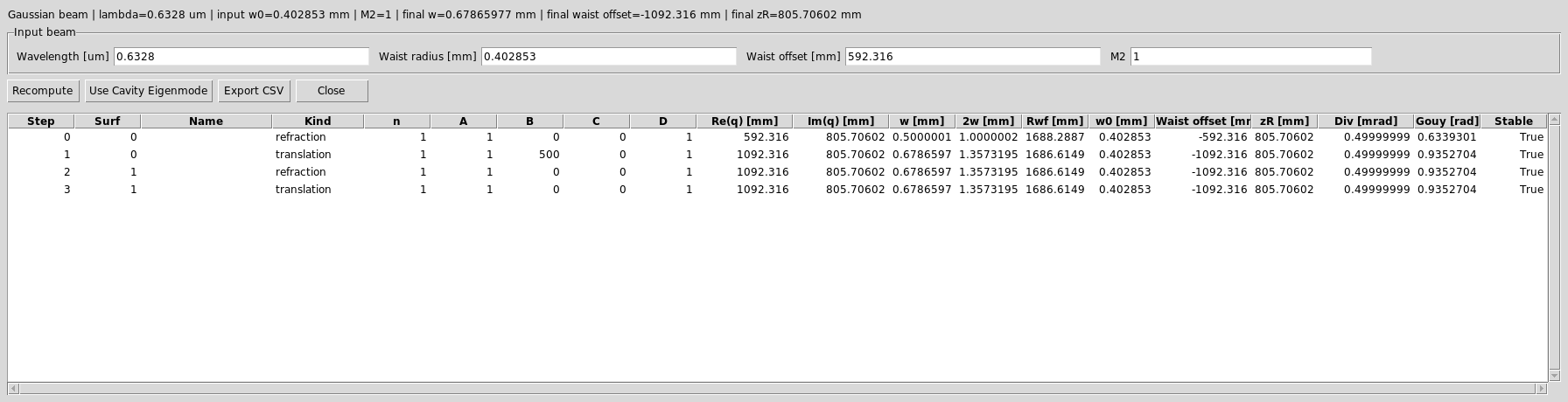
The Gaussian Beam Report lists the ABCD step, q value, beam radius,
wavefront radius, waist offset, Rayleigh range, divergence, and Gouy phase.
Insert A 3x Keplerian Expander
The target is a 3x Keplerian expander. Use two positive lenses separated by
f1 + f2:
magnification = f2 / f1 = 150 / 50 = 3
lens separation = f1 + f2 = 200 mm
Edit the table so it has these rows:
Row |
Surface |
Name |
Rc [mm] |
Thickness [mm] |
Diameter [mm] |
Material |
|---|---|---|---|---|---|---|
0 |
Object |
Laser output |
0 |
80 |
16 |
AIR |
1 |
Thin Lens |
Input lens f=50 |
50 |
200 |
20 |
AIR |
2 |
Thin Lens |
Collimating lens f=150 |
150 |
320 |
45 |
AIR |
3 |
Image |
Readout plane |
0 |
0 |
50 |
AIR |
Practical click path:
Change row
0Thicknessfrom500to80.Click
Add surfacetwice. New rows are inserted beforeImage.For each inserted row, right-click the
Surfacecell and chooseThin Lens.Fill the names,
Rcfocal lengths, thicknesses, and diameters from the table above. The UI will also show an automaticSrc1illumination-source row betweenObjectand the optical surfaces; that row is expected and is not one of the KrakenOS surface rows you are editing.Click
Update.
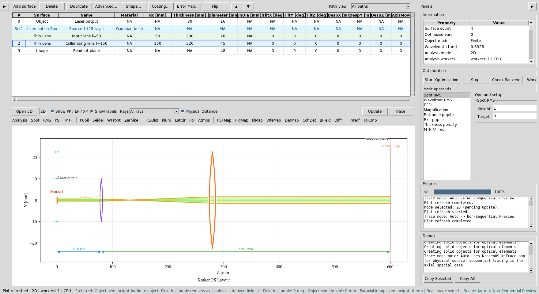
The table now contains the Keplerian expander: f1=50 mm followed by
f2=150 mm.
Thin Lens rows are ideal ABCD lens elements. In the 2-D layout they are
drawn with a purple/orange lens glyph for readability; the glyph width is
not a physical center thickness.
Verify The Expanded Beam
The output beam should be about three times wider and about three times less
divergent than the input beam. Click Update and inspect the Gaussian
envelope.
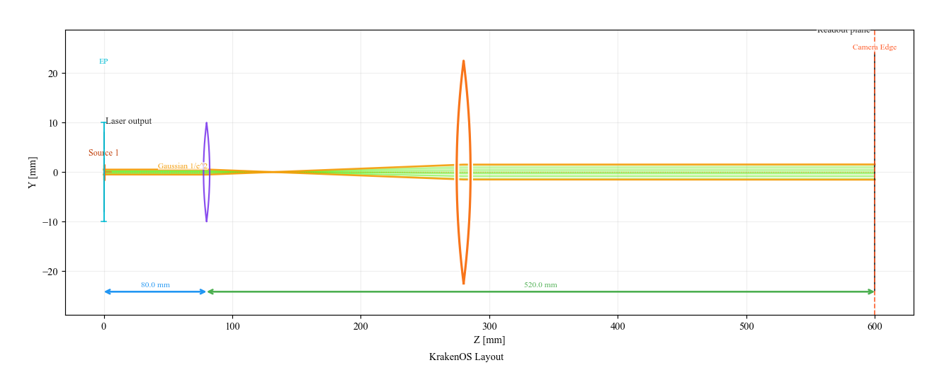
The amber envelope expands through the positive/positive lens pair and then propagates with lower divergence.
Open Actions -> Gaussian Beam Report again. The final readout-plane values
should be close to:
final 1/e^2 diameter ~= 3.09 mm
final half divergence ~= 0.167 mrad
This is the expected 3x beam expansion and 3x divergence reduction.
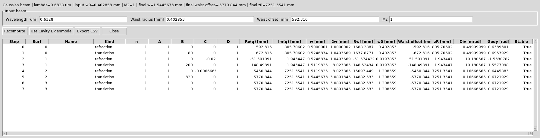
The report verifies the q-parameter propagation through both thin lenses. The final divergence is about one third of the original value.
Run BField Analysis
The Gaussian q report is the paraxial design check. The BField button is
the detector-field check:
Set
Detector bins = 64.Set
Coherent sum = Mutual coherent.Set
BField z [mm] = 0.Click
BFieldand thenUpdate.
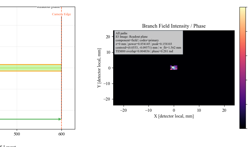
BField promotes the detector samples into the branch-field grid and
plots normalized field intensity, phase contours, centroid, and TEM00
overlap diagnostics.
What This Proves
This case study exercises the laser-specific UI path:
Gaussian source model with physical source position and direction;
laser-datasheet input mode;
automatic waist back-calculation;
1/e² Gaussian envelope overlay in the 2D layout;
Gaussian Beam
Report
/ ABCD q propagation;
thin-lens beam-expander design;
detector-side branch-field analysis.
Common Mistakes
I entered half-angle divergence.The UI field is full divergence in milliradians. A 1 mrad full-angle laser uses
GB full div [mrad] = 1.0.The ordinary Field panel disappeared.That is intentional. For a physical Gaussian source, the source position, direction, diameter, divergence, and power define the illumination.
The Gaussian envelope is not shown.The amber q-envelope overlay is for centered +Z paraxial layouts. For tilted, folded, or beam-splitter layouts, use traced rays plus
Gaussian Beam Report/Branch Gaussian Q Report.The expander output is bigger, so did it make divergence worse?No. A beam expander increases beam diameter and reduces angular divergence. In this example the diameter is about 3x larger and the divergence is about 3x smaller.