Case Study 13: Cube Beam Splitter CAD And Virtual Plane
Goal
This case study documents the current cube beam-splitter workflow without overstating what imported CAD can do:
use a vendor cube CAD/STL body as mechanical geometry;
label the external cube faces;
save a virtual internal 45 degree splitter plane as authoring metadata;
understand why the CAD body alone does not create reflected/transmitted ray branches;
compare that CAD workflow with the validated cube beam-splitter primitive.
The screenshots in this tutorial are generated from the live Tk UI with:
python -m KrakenOS.UI.capture_cube_virtual_plane_case_study_screenshots
The capture script generates a 25 mm cube STL proxy so the tutorial is reproducible without running STEP meshing during documentation builds. The row still records the vendor reference path:
attachment/68551/step_68551.step
Load Or Import The Cube Body
In a live design, choose File -> Import Optical CAD/STL Solid... and select
the vendor cube STEP/STL/IGES file. For this tutorial, the screenshot uses a
generated 25 mm cube proxy with the same row metadata.
The important row is the file-backed Solid_3d_stl optical solid:
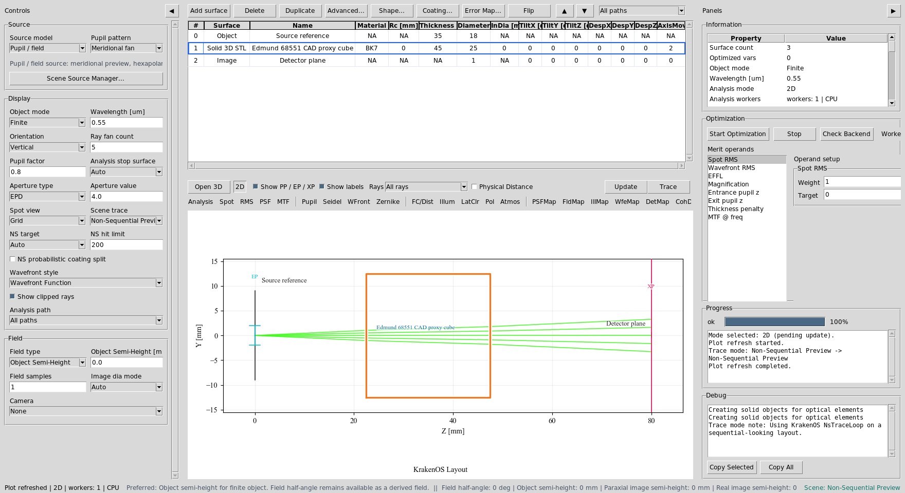
The cube row stores material, pose, the generated STL path, and the original Edmund 68551 STEP source path. It is a real optical solid row, but not yet a traced beam-splitter coating.
Observe The Passive CAD Trace
Click Update with Trace mode = Non-Sequential Preview.
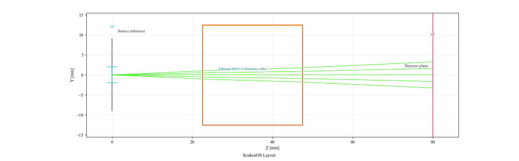
The ray bundle interacts with the closed cube body. It does not split into reflected and transmitted branches because a mechanical CAD file does not encode split ratio, phase, loss, or polarization behavior.
Assign External Faces And Build A Virtual Plane
Select the cube row and choose Actions -> Assign CAD/STL Optical Faces.
Label the external faces:
Left, Right, Up, Down = Transmit/Port
Front, Back           = Absorber/Mechanical or unused mechanical faces
Then use the Virtual Internal Plane workbench:
Diagonal = Left + Up (reflect +Y)
Split    = 0.5
Loss     = 0.02
Phase    = 180 deg
Click Auto Cube Splitter Plane.
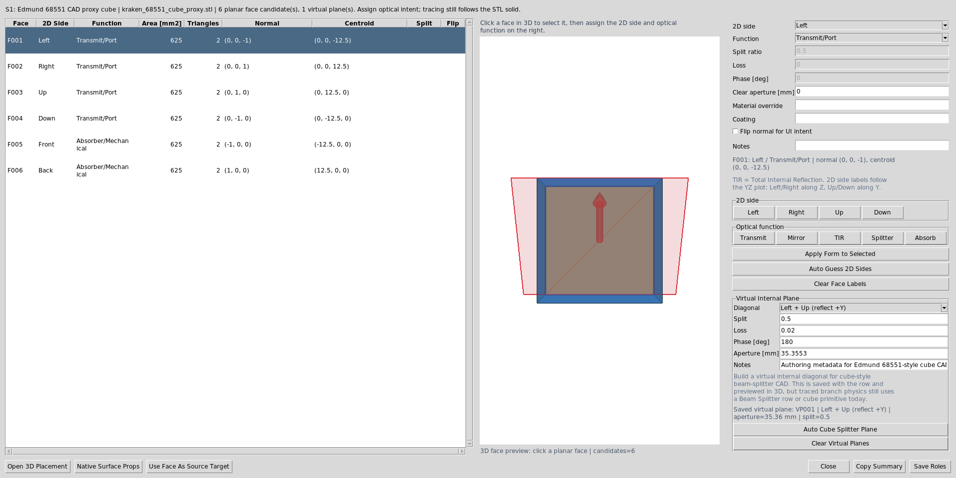
The dialog stores the external face labels and one virtual internal
beam-splitter plane in OpticalSolidFaces metadata. The virtual plane is
visible in 3D preview and placement tools.
Read The Virtual Plane Report
The generated report shows the exact metadata saved for the internal plane.
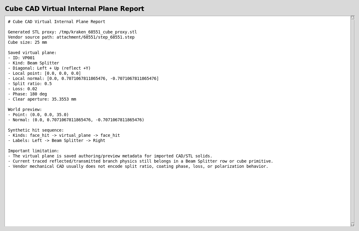
The synthetic hit sequence inserts face_hit -> virtual_plane -> face_hit
between the external Left and Right faces. This is authoring and diagnostic
metadata; it is not yet the active branch-tracing engine for a CAD cube.
Use The Primitive For Splitter Physics Today
For real reflected/transmitted branch physics today, use a Beam Splitter
row or the cube beam-splitter primitive. The Michelson preset uses an Edmund
68551-sized cube reference body plus an internal 45 degree Beam Splitter
row for deterministic 50/50 splitting and recombination.

This is the current validated workflow when reflected/transmitted branches, phase, coherent detector paths, and interferograms matter.
Check Mesh Readiness
The cube proxy used for this tutorial is deliberately simple, but the same mesh diagnostics apply to vendor CAD converted to STL.
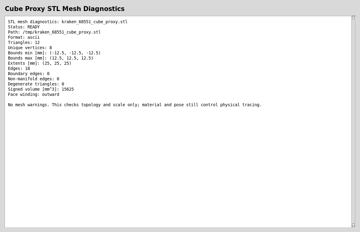
A useful optical CAD/STL body should have finite scale, no open boundary edges, no non-manifold edges, no degenerate triangles, and usable winding.
Run The Validators
Use these checks after changing the virtual-plane, face-role, or hit-sequence code:
python -m KrakenOS.UI.validate_optical_solid_virtual_plane
python -m KrakenOS.UI.validate_optical_solid_hit_sequence
python -m KrakenOS.UI.validate_optical_solid_face_roles
What This Proves
This case study exercises the cube-CAD side of the non-sequential-first architecture:
external cube CAD/STL import as mechanical geometry;
face-role labeling for a closed optical solid;
saved virtual internal splitter-plane metadata;
transformed 3D preview records for the virtual plane;
hit-sequence insertion of a virtual internal plane for diagnostics;
clear separation between CAD authoring intent and active beam-splitter branch physics.
Common Mistakes
I imported a cube STEP and expected it to split rays.A STEP file usually contains only mechanical boundary geometry. It does not contain split ratio, coating phase, loss, or Jones/polarization data. Use a
Beam Splitterrow or cube primitive for active branch physics.I built a virtual internal plane but still see no reflected branch.That is expected today. The virtual plane is saved authoring metadata for preview, placement, and diagnostics. It is a bridge toward CAD-first splitter authoring, not the current traced branch engine.
Can I still use vendor CAD in a real design?Yes. Use it for mechanical envelope, placement, exported STEP overlays, and face/port documentation. Keep the internal
Beam Splitterrow for traced optical behavior until active virtual-plane branch tracing is implemented.Which workflow should I present?Present both: the CAD row proves the UI can import and label real geometry; the Michelson/cube primitive proves the current physics path for splitting, phase, recombination, and interferogram analysis.