Photonics Essentials: Chapter 10 Problems
Source
Thomas P. Pearsall, Photonics Essentials: An Introduction with Experiments
(McGraw-Hill, 2003), Chapter 10, Measurements in Photonics,
Problems 10.1–10.3, printed pages 242–243.
Worked solutions
Problem 10.1: Lock-in amplifier experiment
Brief solution
2. Answer.
This is an experimental protocol, not a problem with one numerical answer. Do not invent the phase or noise readings.
Show detailed steps
This is an experimental protocol, not a problem with one numerical answer. Do not invent the phase or noise readings.
Setup
Mount the silicon photodiode rigidly and connect it to the lock-in input using short, shielded leads.
Place the chopping wheel between a stable visible source and detector.
Connect the chopper reference output to the lock-in reference input.
Start with a long time constant, a sensitivity range that cannot overload, and the manufacturer’s recommended input configuration.
Adjust reference phase for the maximum in-phase signal.
Measurements
Chop frequency |
Time constant |
Source position |
Phase at maximum |
Lock-in amplitude |
Oscilloscope amplitude/noise |
|---|---|---|---|---|---|
Predicted behavior
The lock-in multiplies the detector signal by a phase-coherent reference and low-pass filters the result. A desired sinusoidal component \(V_s\cos(\omega t+\phi)\) produces a DC term proportional to \(V_s\cos\phi\); unrelated light and electrical noise average toward zero.
Moving the source can change optical path, detector capacitance coupling, and signal-to-background ratio, but it should not create a large propagation phase change at laboratory distances. Raising chopping frequency eventually reduces response when the photodiode, amplifier, or selected time constant cannot follow it. Room lighting is strongly rejected unless it contains a component near the reference frequency.
On the oscilloscope, the same chopped signal is visible but rides on broadband noise and ambient-light offsets. This direct comparison demonstrates why phase-sensitive detection can recover a small periodic signal.
Problem 10.2: F-number and aperture angle
Brief solution
1. Method.
For focal length \(f\), clear diameter \(D\), and f-number \(N=f/D\), the marginal-ray half-angle is
2. Key step.
3. Answer.
It decreases monotonically and is approximately \(1/N\) radians for large f-number.
Show detailed steps
For focal length \(f\), clear diameter \(D\), and f-number \(N=f/D\), the marginal-ray half-angle is
Lens |
Half-angle \(\theta\) |
Full cone angle \(2\theta\) |
|---|---|---|
f/2 |
14.04 degrees |
28.07 degrees |
f/5.6 |
5.10 degrees |
10.20 degrees |
f/8 |
3.58 degrees |
7.15 degrees |
The requested plotting function is
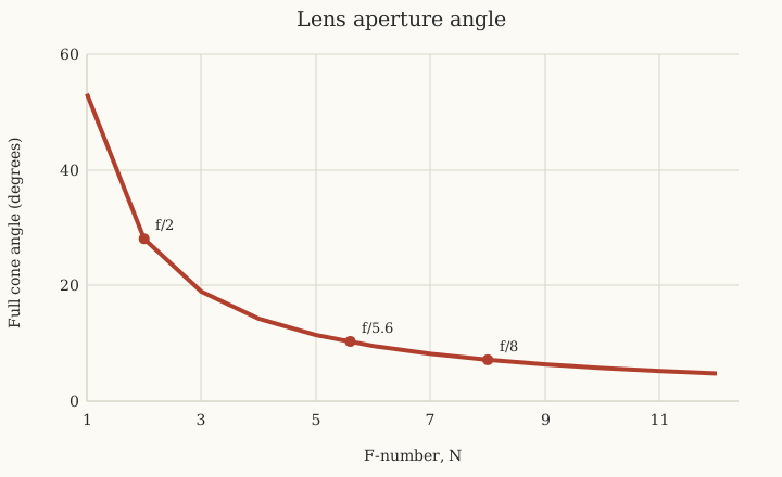
Full cone angle as a function of f-number.
It decreases monotonically and is approximately \(1/N\) radians for large f-number.
Problem 10.3: Filling a screen through a slit
Brief solution
1. Method.
The book’s figure places a \(2\ \mathrm{cm}\) screen \(L=6\ \mathrm{cm}\) behind the slit. Place the lens so that the focused parallel beam forms its waist at the slit. Beyond the waist the cone expands with
2. Key step.
3. Answer.
Thus an f/3 cone exactly fills the one-dimensional screen under the problem’s thin-lens and point-slit assumptions.
Show detailed steps
The book’s figure places a \(2\ \mathrm{cm}\) screen \(L=6\ \mathrm{cm}\) behind the slit. Place the lens so that the focused parallel beam forms its waist at the slit. Beyond the waist the cone expands with
The illuminated height at the screen is
Therefore:
Lens |
Illuminated height at screen |
Fraction of 2 cm screen |
|---|---|---|
f/2 |
3.0 cm |
100% illuminated; 1.0 cm spills outside |
f/4 |
1.5 cm |
75% |
f/8 |
0.75 cm |
37.5% |
To fill the screen exactly,
Thus an f/3 cone exactly fills the one-dimensional screen under the problem’s thin-lens and point-slit assumptions.