Chapter 5: Polarization
Source: Eugene Hecht, Schaum’s Outline of Theory and Problems of Optics (1975), Chapter 5. The entries below cover only the chapter’s Supplementary Problems; prompts are paraphrased and are not reproduced.
Each numbered solution states its assumptions, develops the algebra, substitutes the relevant data, and checks the result. Original SVG illustrations show the ray geometry, field relationships, or calculated curves. Diagrams are schematic unless their axes specify a scale. Source inconsistencies and approximations are identified explicitly rather than silently copied into the answer.
Plane polarization
Formula and definitions.
Remove the common carrier and compare the two complex components. Equal or opposite phases make their ratio real and hence give a fixed line. Its quadrant comes from the component signs; orthogonality is tested by the Jones inner product.
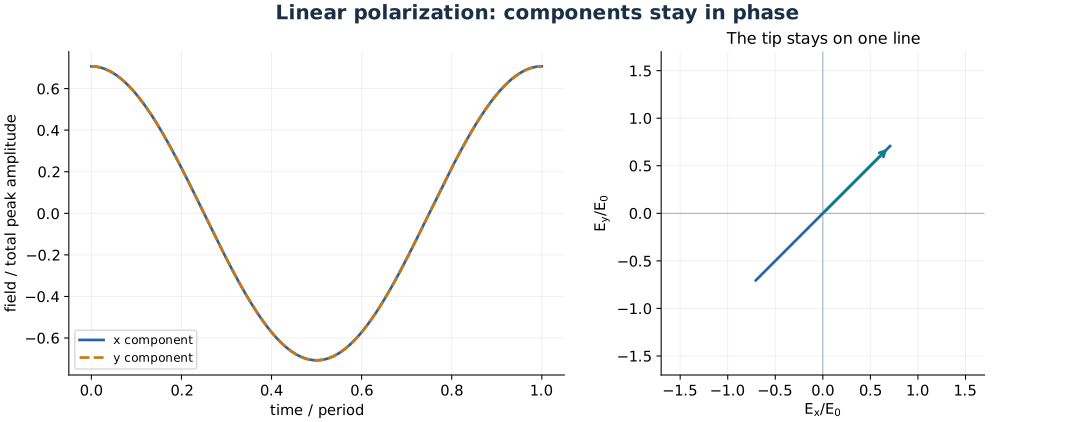
Linear polarization is a fixed transverse direction multiplied by one oscillating scalar amplitude.
Problem 5.48 — write a forty-five-degree linear wave travelling along y
Paraphrased task. Write a forty-five-degree linear wave travelling along y.
Formula reference. Use (1), its definitions, and the topic illustration.
Worked application.
A wave travelling along \(+y\) has phase \(\psi=ky-\omega t=\omega(y/v-t)\) and no longitudinal electric component.
In the transverse \(xz\) plane, a unit vector at \(45^\circ\) is \(\hat{\mathbf e}=(\hat{\mathbf x}+\hat{\mathbf z})/\sqrt2\). The normalization is necessary to keep the total peak amplitude equal to \(E_0\).
Multiply the fixed direction by a harmonic scalar:
\[\mathbf E(y,t)=\frac{E_0}{\sqrt2} (\hat{\mathbf x}+\hat{\mathbf z})\cos[\omega(y/v-t)].\]
Result. A linear state with equal in-phase \(x,z\) components and total amplitude \(E_0\).
Check. \(\mathbf E\cdot\hat{\mathbf y}=0\) and the polarization direction does not change with time.
Problem 5.49 — pass z-polarized light through a y-fast-axis quarter-wave plate
Paraphrased task. Pass z-polarized light through a y-fast-axis quarter-wave plate.
Formula reference. Use (1), its definitions, and the topic illustration.
Worked application.
The incident field lies along \(z\), perpendicular to the plate’s fast \(y\) axis. It therefore excites only the slow eigenpolarization.
In the \((y,z)\) basis, the incident Jones vector is proportional to \((0,1)\). A quarter-wave plate multiplies the two components by different phase factors, but a zero component remains zero.
After removing the common phase or redefining the time origin, the emerging field is \(\mathbf E(x,t)=E_0\hat{\mathbf z}\cos(kx-\omega t)\). No orthogonal component is created.
Result. The light remains linearly polarized along \(z\), with unchanged amplitude for an ideal lossless plate.
Check. A quarter-wave plate makes circular light only when both eigenaxes receive equal nonzero amplitudes.
Problem 5.50 — write an xy-plane linear wave with zero initial field
Paraphrased task. Write an xy-plane linear wave with zero initial field.
Formula reference. Use (1), its definitions, and the topic illustration.
Worked application.
Propagation is along \(y\); a vibration plane equal to \(xy\) therefore requires the electric field to point along \(x\).
Use phase \(ky-\omega t\) for propagation toward \(+y\). The specified zero field at the origin rules out a zero-phase cosine but permits a sine.
One convenient expression is \(\mathbf E(y,t)=E_0\hat{\mathbf x}\sin(ky-\omega t)\). Its value at \(y=t=0\) is zero and its maximum magnitude is \(E_0\).
Result. \(\mathbf E=E_0\hat{\mathbf x}\sin(ky-\omega t)\).
Check. Changing the overall sign gives another valid initial-phase choice with the same polarization and speed.
Problem 5.51 — classify a signed two-component linear wave
Paraphrased task. Classify a signed two-component linear wave.
Formula reference. Use (1), its definitions, and the topic illustration.
Worked application.
Factor the common oscillation: \(\mathbf E=-E_0(\sqrt3\hat{\mathbf x}+\hat{\mathbf z})\cos(ky+\omega t)\).
The coefficient vector is constant, so the polarization is linear. Its magnitude is \(E_0\sqrt{3+1}=2E_0\) and its component ratio is \(|E_x/E_z|=\sqrt3\).
The polarization line therefore makes \(\arctan\sqrt3=60^\circ\) with the \(z\) direction in the transverse plane, hence with the \(yz\) vibration plane. Constant phase gives \(dy/dt=-\omega/k\), so propagation is toward \(-y\).
Result. A linear wave of amplitude \(2E_0\), propagating toward \(-y\), with vibration plane tilted \(60^\circ\) from \(yz\).
Check. The common minus sign is a phase shift of \(\pi\), not a different polarization axis.
Problem 5.52 — write a linear wave tilted 17.5 degrees above the xy plane
Paraphrased task. Write a linear wave tilted 17.5 degrees above the xy plane.
Formula reference. Use (1), its definitions, and the topic illustration.
Worked application.
For propagation along \(x\), the transverse reference direction in the \(xy\) plane is \(y\).
Tilt toward \(z\) by \(17.5^\circ\), giving unit vector \(\hat{\mathbf e}=\hat{\mathbf y}\cos17.5^\circ+\hat{\mathbf z}\sin17.5^\circ\).
Thus \(\mathbf E(x,t)=E_0(0.953717\hat{\mathbf y}+0.300706\hat{\mathbf z})\cos(kx-\omega t)\); the two components have the same phase.
Result. Use the normalized direction \(0.9537\hat{\mathbf y}+0.3007\hat{\mathbf z}\).
Check. \(0.953717^2+0.300706^2\approx1\), so \(E_0\) is the total, not component, amplitude.
Circular polarization
Formula and definitions.
Circular polarization requires equal component magnitudes and quadrature phase. Evaluate the real field at a fixed \(z\) for increasing \(t\) to determine handedness under the book’s viewing convention. A quarter-wave plate supplies the required \(\pm\pi/2\) phase delay.
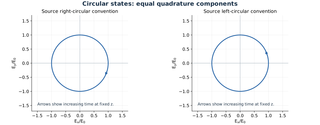
Opposite circular states trace the same circle but rotate in opposite directions at a fixed observation point.
Problem 5.53 — superpose two in-phase linear waves of unequal amplitude
Paraphrased task. Superpose two in-phase linear waves of unequal amplitude.
Formula reference. Use (2), its definitions, and the topic illustration.
Worked application.
Represent the common left-circular waveform by a unit rotating vector \(\mathbf u_L(\psi)=(\cos\psi,-\sin\psi)\) in the transverse plane.
The two fields are \(2E_0\mathbf u_L\) and \(E_0\mathbf u_L\). Equal phase and handedness mean their vectors are parallel at every instant.
Add fields before squaring: \(\mathbf E=3E_0\mathbf u_L\). The irradiance is nine times that of the \(E_0\) wave alone, not five times, because the coherent cross term contributes.
Result. Left-circular light of amplitude \(3E_0\).
Check. For a nonzero relative phase, the circular handedness survives but the resultant amplitude becomes \(E_0\sqrt{5+4\cos\delta}\).
Problem 5.54 — devise a test that distinguishes right- from left-circular light
Paraphrased task. Devise a test that distinguishes right- from left-circular light.
Formula reference. Use (2), its definitions, and the topic illustration.
Worked application.
A rotating linear analyzer alone transmits half the irradiance of either circular handedness; it cannot distinguish them.
First insert a calibrated quarter-wave plate. In a fixed propagation and fast-axis convention, opposite circular states become orthogonal linear states.
Align a linear analyzer to the output direction known to correspond to right-circular input. Right-circular light is transmitted and left-circular light is extinguished; rotate the analyzer by \(90^\circ\) to interchange the outcomes. Calibration avoids ambiguity between competing handedness naming conventions.
Result. Use a quarter-wave plate followed by a linear analyzer, with known fast-axis orientation and viewing direction.
Check. Reversing propagation or viewing direction can reverse a verbal right/left label; the measured orthogonal analyzer outputs remain unambiguous.
Problem 5.55 — write a right-circular wave with a specified initial azimuth
Paraphrased task. Write a right-circular wave with a specified initial azimuth.
Formula reference. Use (2), its definitions, and the topic illustration.
Worked application.
Use \(\psi=kz-\omega t\). In the source convention, right-circular light has transverse field \(E_0(\cos\phi,\sin\phi)\) with \(\phi=\psi+\phi_0\).
At the origin the direction angle is \(\phi_0\); choose \(\phi_0=-\pi/4\) to meet the requested \(-45^\circ\) initial orientation.
The field is
\[\mathbf E=E_0[\hat{\mathbf x}\cos(\psi-\pi/4) +\hat{\mathbf y}\sin(\psi-\pi/4)].\]At fixed \(z\), the angle decreases as time increases, explicitly fixing the rotation convention.
Result. The above circular field starts at \(E_0(\hat{\mathbf x}-\hat{\mathbf y})/\sqrt2\).
Check. \(E_x^2+E_y^2=E_0^2\) at every time, not merely on average.
Problem 5.56 — write a right-circular wave from a specified initial vector
Paraphrased task. Write a right-circular wave from a specified initial vector.
Formula reference. Use (2), its definitions, and the topic illustration.
Worked application.
The initial vector \(E_0(\hat{\mathbf x}+\sqrt3\hat{\mathbf y})/2\) has unit direction \((\cos\pi/3,\sin\pi/3)\).
For the same right-circular convention as Problem 5.55, set \(\phi=kz-\omega t+\pi/3\) in both components.
Hence \(\mathbf E=E_0[\hat{\mathbf x}\cos\phi+\hat{\mathbf y}\sin\phi]\). Substituting the origin gives the requested vector, while \(|\mathbf E|=E_0\) proves circularity. The mismatched phase signs in the printed endpoint would not give constant magnitude.
Result. Use a common phase \(kz-\omega t+\pi/3\) inside the cosine and sine.
Check. Checking only the initial vector is insufficient: an incorrect elliptic waveform can pass through the same initial point.
Problem 5.57 — write a left-circular wave with a specified initial azimuth
Paraphrased task. Write a left-circular wave with a specified initial azimuth.
Formula reference. Use (2), its definitions, and the topic illustration.
Worked application.
Left-circular light in the source convention is \(E_0(\cos\phi,-\sin\phi)\) with \(\phi=kz-\omega t+\phi_0\).
Its geometric field angle at the origin is \(-\phi_0\). To start at \(+30^\circ\), choose \(\phi_0=-\pi/6\).
The required field is \(\mathbf E=E_0[\hat{\mathbf x}\cos(kz-\omega t-\pi/6)-\hat{\mathbf y}\sin(kz-\omega t-\pi/6)]\). At fixed position its angle increases with time, opposite to Problem 5.55.
Result. The initial field is \(E_0(\sqrt3\hat{\mathbf x}+\hat{\mathbf y})/2\).
Check. The printed task specifies \(30^\circ\); some OCR copies misread this as \(80^\circ\).
Elliptical polarization
Formula and definitions.
Write one component as \(E_{0x}\cos\tau\) and the other as \(E_{0y}\cos(\tau+\delta)\). Expanding the latter and eliminating \(\sin\tau\) gives the quadratic ellipse. Diagonalizing its symmetric quadratic form gives principal axes and azimuth.
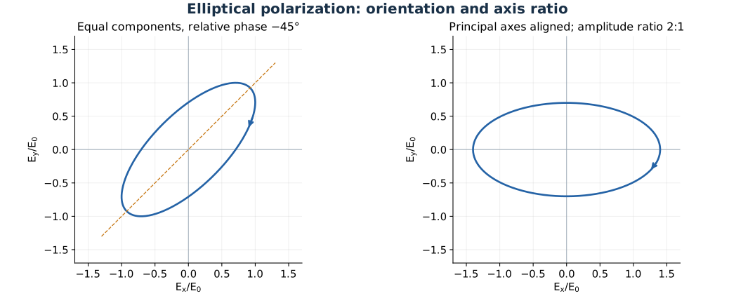
Relative phase and component amplitudes determine the ellipse orientation and the ratio of its principal axes.
Problem 5.58 — write a right-handed ellipse tilted to the y axis
Paraphrased task. Write a right-handed ellipse tilted to the y axis.
Formula reference. Use (3), its definitions, and the topic illustration.
Worked application.
Work in the right-handed transverse \((y,z)\) plane for propagation along \(+x\), with \(\psi=kx-\omega t\).
Choose equal component amplitudes and relative phase \(-\pi/4\): \(E_y=E_0\cos\psi\), \(E_z=E_0\cos(\psi-\pi/4)\).
In coordinates \(U=(E_y+E_z)/\sqrt2\), \(V=(E_y-E_z)/\sqrt2\), the squared semiaxes are \(E_0^2(1+1/\sqrt2)\) and \(E_0^2(1-1/\sqrt2)\). The longer axis is \(y=z\), at \(45^\circ\); the negative phase offset gives the source’s right-handed rotation.
Result. \(\mathbf E=E_0\hat{\mathbf y}\cos\psi+E_0\hat{\mathbf z}\cos(\psi-\pi/4)\) is one valid tilted ellipse.
Check. Equal Cartesian amplitudes do not imply a circle unless the relative phase is \(\pm\pi/2\).
Problem 5.59 — write a left-handed ellipse with major axis at 135 degrees
Paraphrased task. Write a left-handed ellipse with major axis at 135 degrees.
Formula reference. Use (3), its definitions, and the topic illustration.
Worked application.
Set \(\psi=kz-\omega t\), \(E_x=E_0\cos\psi\), and \(E_y=E_0\cos(\psi+3\pi/4)\).
The equal-amplitude ellipse has axes along \(x=y\) and \(x=-y\). Since \(\cos(3\pi/4)<0\), the larger squared semiaxis is \(E_0^2[1-\cos(3\pi/4)]\), along \(x=-y\).
Thus the major-axis orientation is \(135^\circ\) modulo \(180^\circ\). At fixed position the positive relative cosine phase produces the left-handed sense used in this chapter.
Result. \(\mathbf E=E_0[\hat{\mathbf x}\cos\psi+\hat{\mathbf y}\cos(\psi+3\pi/4)]\).
Check. The major/minor axis ratio is \(\sqrt{(1+1/\sqrt2)/(1-1/\sqrt2)}=1+\sqrt2\).
Problem 5.60 — classify an ellipse from two phase-shifted components
Paraphrased task. Classify an ellipse from two phase-shifted components.
Formula reference. Use (3), its definitions, and the topic illustration.
Worked application.
The given phase is \(q=\omega(t-z/v)=-\psi\), not \(\psi=kz-\omega t\). Rewrite \(E_x=E_0\cos\psi\) and \(E_y=E_0\cos(\psi+5\pi/4)=E_0\cos(\psi-3\pi/4)\).
The amplitudes are equal and the phase difference is neither zero nor a multiple of \(\pi/2\), so the state is elliptical. Because \(\cos(-3\pi/4)=-1/\sqrt2\), the major axis is along \(x=-y\).
The negative sine of the relative phase gives the same rotation sense as the right-handed state of Problem 5.58. The major axis is at \(135^\circ\) and its axial ratio is \(1+\sqrt2\).
Result. A right-handed ellipse, major axis at \(135^\circ\), propagating toward \(+z\).
Check. Reversing the sign of the common time phase without changing the relative-phase interpretation reverses an inferred handedness incorrectly.
Problem 5.61 — write a right-handed two-to-one ellipse along x
Paraphrased task. Write a right-handed two-to-one ellipse along x.
Formula reference. Use (3), its definitions, and the topic illustration.
Worked application.
To put the principal axes along \(x,y\), choose components in quadrature rather than an arbitrary phase difference.
Give the \(x\) component twice the amplitude of the \(y\) component. With \(\psi=kz-\omega t\), take \(\mathbf E=2E_0\hat{\mathbf x}\cos\psi+E_0\hat{\mathbf y}\sin\psi\).
Eliminating the phase yields \(E_x^2/(2E_0)^2+E_y^2/E_0^2=1\). The major axis is \(x\), the axial ratio is 2, and the field rotates in the right-handed convention of Problem 5.55.
Result. \(\mathbf E=2E_0\hat{\mathbf x}\cos(kz-\omega t)+E_0\hat{\mathbf y}\sin(kz-\omega t)\).
Check. The semiaxis ratio is 2, while the corresponding squared-amplitude ratio is 4.
Problem 5.62 — decompose an ellipse into linear and circular components
Paraphrased task. Decompose an ellipse into linear and circular components.
Formula reference. Use (3), its definitions, and the topic illustration.
Worked application.
Let \(\psi=kz-\omega t\) and suppose first that \(E_{0x}\ge E_{0y}\ge0\). Add and subtract \(E_{0y}\hat{\mathbf x}\sin\psi\).
The given ellipse separates exactly into
\[\mathbf E=(E_{0x}-E_{0y})\hat{\mathbf x}\sin\psi +E_{0y}(\hat{\mathbf x}\sin\psi+\hat{\mathbf y}\cos\psi).\]The first term has a fixed direction and is linear. The second has equal quadrature components and constant magnitude, so it is circular. If \(E_{0y}>E_{0x}\), instead remove a circular field of amplitude \(E_{0x}\) and leave the excess along \(y\).
Result. The ellipse is a coherent sum of a circular component of the smaller semiaxis amplitude and a linear residual.
Check. These fields are coherent; their irradiances cannot in general be added as though they were an incoherent statistical mixture.
Natural and partially polarized light
Formula and definitions.
An ideal analyzer transmits half of the unpolarized component and the Malus-law projection of the polarized component. Evaluating at parallel and crossed orientations gives \(I_{\max}\) and \(I_{\min}\); their sum and difference isolate \(I_u\) and \(I_p\).
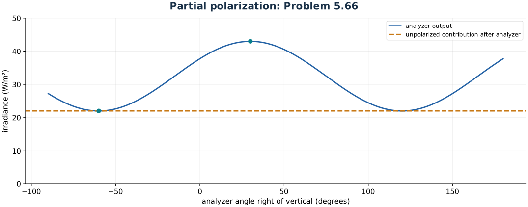
Problem 5.66: the analyzer scan separates a polarized contribution from an angle-independent unpolarized background.
Problem 5.63 — decide whether a perfectly monochromatic wave must be polarized
Paraphrased task. Decide whether a perfectly monochromatic wave must be polarized.
Formula reference. Use (4), its definitions, and the topic illustration.
Worked application.
For a single deterministic plane wave at exactly one frequency, write \(\mathbf E=\operatorname{Re}[(A_x\hat{\mathbf x}+A_y\hat{\mathbf y})e^{i(kz-\omega t)}]\) with constant complex amplitudes.
The amplitude ratio and relative phase are fixed. Eliminating time gives a fixed ellipse, including the linear and circular limiting cases: the wave has a definite polarization.
In the source’s wave-train model, a randomly changing polarization requires time-dependent amplitudes or phases, hence a finite spectral width. The claim applies to a single coherent mode; an ensemble or unresolved superposition of modes needs a statistical polarization description and should not be inferred from a narrow measured spectrum alone.
Result. An exactly monochromatic, single deterministic plane wave is fully polarized.
Check. A stationary narrowband beam can nevertheless be partially or wholly unpolarized when incoherent modes are averaged.
Problem 5.64 — distinguish partially linear from partially elliptical light
Paraphrased task. Distinguish partially linear from partially elliptical light.
Formula reference. Use (4), its definitions, and the topic illustration.
Worked application.
Rotate a linear analyzer to identify the principal-axis direction \(\alpha\) of the polarized contribution. Write its Jones vector in these axes as \((a,ib)\); add an incoherent natural background of irradiance \(I_u\).
Align a quarter-wave plate to these axes. If the contribution is linear, \(b=0\), so the plate changes no relative phase between nonzero components and the analyzer extrema stay on the same axes.
If it is genuinely elliptical, \(a,b\ne0\); the plate converts the quadrature components to an in-phase or antiphase pair \((a,\pm b)\). The polarized output is now linear at \(\arctan(\pm b/a)\), and the analyzer’s extrema shift. The natural component stays natural.
Result. Compare analyzer scans before and after an axis-aligned quarter-wave plate; a shifted principal direction reveals an elliptical contribution.
Check. A circular contribution has no initial preferred analyzer direction; the quarter-wave plate still turns it into a detectable linear contribution.
Problem 5.65 — distinguish natural, circular, and mixed light experimentally
Paraphrased task. Distinguish natural, circular, and mixed light experimentally.
Formula reference. Use (4), its definitions, and the topic illustration.
Worked application.
Let the incident beam contain circular irradiance \(I_c\) and unpolarized irradiance \(I_u\). A quarter-wave plate converts the circular part into linear light but leaves the unpolarized part unchanged.
A following analyzer at angle \(\theta\) to that linear direction transmits \(I(\theta)=I_c\cos^2\theta+I_u/2\).
Thus \(I_{\max}=I_c+I_u/2\) and \(I_{\min}=I_u/2\). A zero minimum means purely circular input; equal maximum and minimum mean natural input; a positive minimum smaller than the maximum means a mixture.
Result. After the quarter-wave plate, measure \(I_c=I_{\max}-I_{\min}\) and \(I_u=2I_{\min}\).
Check. Without the retarder all three possibilities give angle-independent transmission through a linear analyzer.
Problem 5.66 — recover polarization degree from two analyzer readings
Paraphrased task. Recover polarization degree from two analyzer readings.
Formula reference. Use (4), its definitions, and the topic illustration.
Worked application.
The two stated analyzer orientations, \(30^\circ\) right and \(60^\circ\) left of vertical, differ by \(90^\circ\). They therefore give the maximum and minimum: 43 and \(22\,\mathrm{W\,m^{-2}}\).
For a linear-plus-natural mixture, \(I_p=I_{\max}-I_{\min}=21\) and \(I_u=2I_{\min}=44\,\mathrm{W\,m^{-2}}\).
The degree of polarization is
\[V=\frac{I_p}{I_p+I_u} =\frac{43-22}{43+22}=\frac{21}{65}=0.32308.\]
Result. The beam is \(32.3\%\) polarized.
Check. The incident total is \(65\,\mathrm{W\,m^{-2}}\), not the maximum analyzer reading of 43.
Dichroism and Polaroid
Formula and definitions.
The first ideal polarizer transmits half of natural incident light. Every later plate receives a linearly polarized beam, so apply Malus’s law using the angle relative to the immediately preceding transmission axis, not the first axis.
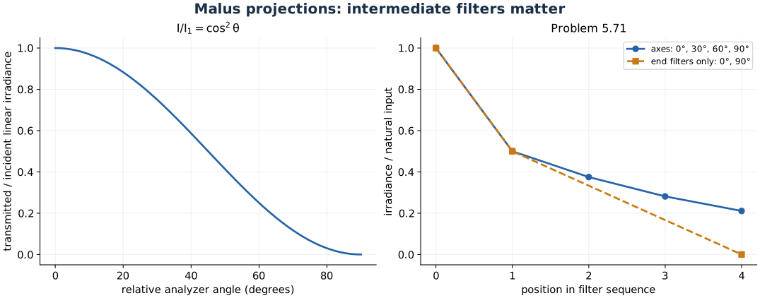
Successive Malus projections explain why intermediate polarizers transmit light between crossed end polarizers.
Problem 5.67 — write the field transmitted from natural light by one polarizer
Paraphrased task. Write the field transmitted from natural light by one polarizer.
Formula reference. Use (5), its definitions, and the topic illustration.
Worked application.
An ideal linear polarizer transmits half the unpolarized irradiance, so \(I_o=I_i/2\). Its transmission unit vector is \((\hat{\mathbf y}+\hat{\mathbf z})/\sqrt2\).
For a harmonic representative in vacuum, \(I_o=\epsilon_0cE_0^2/2\); hence the total peak field is \(E_0=\sqrt{I_i/(\epsilon_0c)}\).
A suitable linearly polarized wave is
\[\mathbf E(x,t)=\sqrt{\frac{I_i}{2\epsilon_0c}} (\hat{\mathbf y}+\hat{\mathbf z}) \sin\left(\frac{2\pi x}{\lambda}-\omega t\right).\]Real filtered natural light has a fluctuating scalar amplitude/phase; this harmonic expression specifies the direction and intensity normalization, not a new temporal coherence imposed by the polarizer.
Result. The output is linear at \(45^\circ\) in the \(yz\) plane and has irradiance \(I_i/2\).
Check. Sum both squared component amplitudes before using \(I=\epsilon_0cE_0^2/2\).
Problem 5.68 — compare Malus transmission at thirty and sixty degrees
Paraphrased task. Compare malus transmission at thirty and sixty degrees.
Formula reference. Use (5), its definitions, and the topic illustration.
Worked application.
Let \(I_1\) be the irradiance immediately after the first polarizer. It is the same in both measurements.
Malus’s law gives \(I(30^\circ)=I_1\cos^230^\circ=3I_1/4\) and \(I(60^\circ)=I_1\cos^260^\circ=I_1/4\).
Divide the two expressions; the first polarizer’s transmission and the original source irradiance cancel.
Result. \(I(30^\circ)/I(60^\circ)=3\).
Check. Use the angle between the two transmission axes, not an angle relative to the incident propagation direction.
Problem 5.69 — propagate irradiance through three specified polarizers
Paraphrased task. Propagate irradiance through three specified polarizers.
Formula reference. Use (5), its definitions, and the topic illustration.
Worked application.
Assume the incident beam is unpolarized. The first polarizer at \(0^\circ\) leaves \(I_i/2\).
The next axis differs by \(36^\circ\); the final axis differs from the second by \(76^\circ-36^\circ=40^\circ\), not \(76^\circ\).
Multiply the successive transmissions: \(I_o=(I_i/2)\cos^236^\circ\cos^240^\circ=0.19204I_i\).
Result. \(I_o\approx0.1920I_i\) for natural input.
Check. Each polarizer resets the output polarization direction, so each projection is relative to its immediate predecessor.
Problem 5.70 — propagate irradiance through ten forty-five-degree stages
Paraphrased task. Propagate irradiance through ten forty-five-degree stages.
Formula reference. Use (5), its definitions, and the topic illustration.
Worked application.
The first ideal polarizer reduces natural input to \(I_i/2\) and creates a linear state.
Each of the remaining \(N-1\) polarizers is at \(45^\circ\) to the preceding one and contributes \(\cos^245^\circ=1/2\).
Therefore \(I_o=(I_i/2)(1/2)^{N-1}=I_i2^{-N}\). For ten polarizers, \(2^{-10}=1/1024=9.765625\times10^{-4}\).
Result. \(I_o=2^{-N}I_i\); for ten filters, \(I_o=9.77\times10^{-4}I_i\).
Check. There are nine inter-axis projections for ten filters, plus the initial factor of one half.
Problem 5.71 — compare four-polarizer transmission with crossed endpoints
Paraphrased task. Compare four-polarizer transmission with crossed endpoints.
Formula reference. Use (5), its definitions, and the topic illustration.
Worked application.
The four axes may be written \(0^\circ,30^\circ,60^\circ,90^\circ\). Natural input loses half its irradiance at the first filter.
Three successive projections give \(I_o=(I_i/2)(\cos^230^\circ)^3=(I_i/2)(3/4)^3=27I_i/128\).
Removing the middle two leaves the \(0^\circ\) and \(90^\circ\) filters directly crossed, giving \(I_o=(I_i/2)\cos^290^\circ=0\).
Result. All four transmit \(0.21094I_i\); the two end filters alone transmit zero.
Check. Additional intermediate polarizers can increase transmission through crossed endpoints by changing the state between projections.
Problem 5.72 — explain extinction for a reordered three-polarizer stack
Paraphrased task. Explain extinction for a reordered three-polarizer stack.
Formula reference. Use (5), its definitions, and the topic illustration.
Worked application.
Assign orientations \(\alpha_1=0^\circ\), \(\alpha_2=+45^\circ\), and \(\alpha_3=-45^\circ\).
In the order 1, 2, 3, the last two axes differ by \(90^\circ\), so their Malus factor is zero regardless of the initial irradiance.
In the comparison order 2, 1, 3, each adjacent angle is \(45^\circ\); unpolarized incident light would transmit \((I_i/2)(1/2)(1/2)=I_i/8\). Polarizer order therefore matters.
Result. No light emerges in the stated 1–2–3 order.
Check. Polarization projections do not commute; the same set of filters can transmit a different irradiance when reordered.
Polarization by reflection
Formula and definitions.
At Brewster incidence the reflected and transmitted rays are orthogonal. Substituting that condition into Snell’s law gives the tangent rule. For natural light, apply the separate Fresnel reflectances to equal incident s and p irradiances, then form the polarization degree.
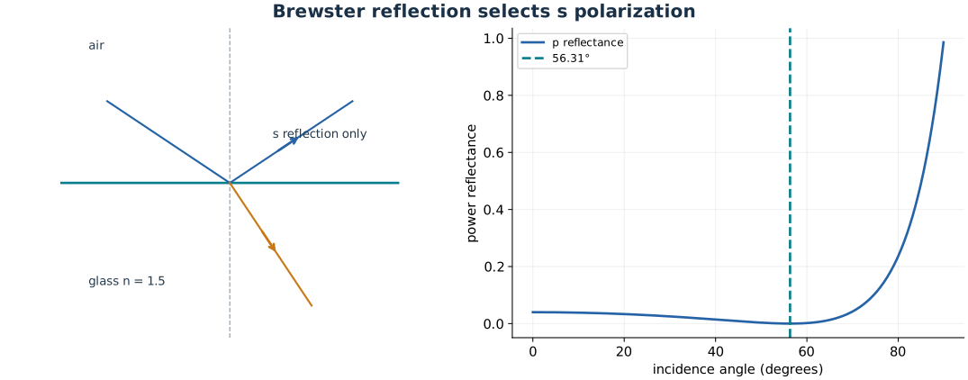
At Brewster incidence the p reflection vanishes, and the reflected and transmitted ray directions are perpendicular.
Problem 5.73 — infer glass index from a measured Brewster angle
Paraphrased task. Infer glass index from a measured brewster angle.
Formula reference. Use (6), its definitions, and the topic illustration.
Worked application.
Complete reflected linear polarization at a lossless dielectric interface identifies the Brewster angle, where the p reflection coefficient vanishes.
Brewster’s law is \(\tan\theta_B=n_g/n_{\rm air}\). Convert \(58^\circ01'=58+1/60=58.016667^\circ\).
With \(n_{\rm air}\approx1\), \(n_g=\tan58.016667^\circ\approx1.60137\). This is the index at the specified mercury wavelength, not a wavelength-independent material constant.
Result. \(n_g\approx1.6014\) at \(546.072\,\mathrm{nm}\).
Check. At Brewster incidence, the reflected field is s-polarized, parallel to the interface and perpendicular to the incidence plane.
Problem 5.74 — calculate external Brewster and transmitted angles
Paraphrased task. Calculate external brewster and transmitted angles.
Formula reference. Use (6), its definitions, and the topic illustration.
Worked application.
For air to crown glass, \(\theta_B=\arctan(1.5170)=56.6074^\circ\).
At Brewster incidence, Snell’s law and \(\tan\theta_B=n_t/n_i\) imply \(\theta_t=90^\circ-\theta_B=33.3926^\circ\).
Converting fractional degrees to arcminutes gives approximately \(56^\circ36'\) for incidence and \(33^\circ24'\) inside the plate.
Result. \(\theta_B\approx56.61^\circ\), \(\theta_t\approx33.39^\circ\).
Check. The transmitted and reflected ray directions are perpendicular at Brewster incidence.
Problem 5.75 — derive Malus variation from two reflecting plates
Paraphrased task. Derive malus variation from two reflecting plates.
Formula reference. Use (6), its definitions, and the topic illustration.
Worked application.
The first Brewster reflection selects the component perpendicular to its incidence plane, leaving a linearly polarized beam.
Rotating the second incidence plane around this beam by \(\theta\) rotates that plate’s s direction by the same angle. Project the incident field onto it: \(E_{s2}=E_1\cos\theta\).
The p reflection is zero, so only \(E_{s2}\) contributes. Squaring and including the fixed s reflectance gives \(I_2(\theta)=R_{s2}I_1\cos^2\theta=I_2(0)\cos^2\theta\).
Result. The second reflected irradiance follows \(I_2(\theta)=I_2(0)\cos^2\theta\).
Check. The Brewster incidence angle must stay fixed during the rotation; otherwise the Fresnel factor also changes.
Problem 5.76 — calculate reflected and transmitted degrees of polarization
Paraphrased task. Calculate reflected and transmitted degrees of polarization.
Formula reference. Use (6), its definitions, and the topic illustration.
Worked application.
Resolve natural incident light into equal incoherent s and p irradiances \(I_i/2\). At Brewster incidence, \(R_p=0\) while \(R_s=0.15\).
The reflected components are \(0.075I_i\) and zero, so \(V_r=1\). For a lossless interface the power transmittances are \(T_s=0.85\) and \(T_p=1\).
The common geometric conversion from normal power flux to transmitted beam irradiance cancels in the ratio:
\[V_t=\frac{T_p-T_s}{T_p+T_s} =\frac{1-0.85}{1+0.85}=0.081081.\]
Result. Reflected light: \(100\%\) polarized; transmitted light: \(8.11\%\) polarized, with p predominating.
Check. Complete polarization of the weak reflected beam does not imply complete polarization of the much stronger transmitted beam.
Problem 5.77 — compare internal and external Brewster angles
Paraphrased task. Compare internal and external brewster angles.
Formula reference. Use (6), its definitions, and the topic illustration.
Worked application.
For incidence from water onto flint glass, use the relative index: \(\theta_{B,\rm ext}=\arctan(1.673/1.333)\approx51.45^\circ\).
For incidence from inside the glass, reverse the index ratio: \(\theta_{B,\rm int}=\arctan(1.333/1.673)\approx38.55^\circ\).
Since the two ratios are reciprocal and positive, their arctangents sum to \(90^\circ\). Rounded to arcminutes the pair is approximately \(51^\circ27'\) and \(38^\circ33'\).
Result. External Brewster angle \(51.45^\circ\); internal Brewster angle \(38.55^\circ\).
Check. Using the glass index alone would calculate an air-glass angle and is inappropriate for a plate immersed in water.
Birefringence
Formula and definitions.
Resolve the incident Jones vector onto the fast and slow axes, apply their relative phase delay, and rotate back. Quarter-, half-, and full-wave behavior corresponds to \(\Delta\phi=\pi/2\), \(\pi\), and \(2\pi\) modulo \(2\pi\). Minimum-deviation prism data gives each principal index through the prism formula.
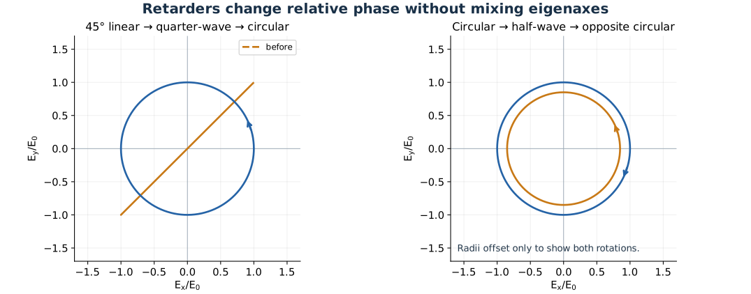
A quarter-wave plate changes the phase relation between eigenaxis components; a half-wave plate reverses circular handedness.
Problem 5.78 — pass right-circular light through a vertical-fast-axis quarter-wave plate
Paraphrased task. Pass right-circular light through a vertical-fast-axis quarter-wave plate.
Formula reference. Use (7), its definitions, and the topic illustration.
Worked application.
Use real fields \(E_x=E_0\cos\psi\), \(E_y=E_0\sin\psi\) for right-circular input, with \(\psi=kz-\omega t\).
The fast axis is \(y\), so relative to that component the slow \(x\) component acquires an extra propagation phase \(\pi/2\). Removing the common phase gives \(E_x'=E_0\cos(\psi+\pi/2)=-E_0\sin\psi\), \(E_y'=E_0\sin\psi\).
Both components now share the same scalar oscillation and have opposite signs. The polarization line is \(y=-x\), or \(135^\circ\) from \(x\) modulo \(180^\circ\).
Result. The output is linear at \(135^\circ\) to the horizontal.
Check. The angle refers to an unoriented polarization line: \(135^\circ\) and \(-45^\circ\) describe the same state.
Problem 5.79 — pass left-circular light through the same plate
Paraphrased task. Pass left-circular light through the same plate.
Formula reference. Use (7), its definitions, and the topic illustration.
Worked application.
Left-circular input has \(E_x=E_0\cos\psi\), \(E_y=-E_0\sin\psi\) in the convention used here.
With a vertical fast axis, add \(\pi/2\) to the slow x-component phase: \(E_x'=-E_0\sin\psi\), while \(E_y'=-E_0\sin\psi\) after dropping a common phase.
The two components are now equal and in phase. Their sum points along \(\hat{\mathbf x}+\hat{\mathbf y}\), a fixed \(45^\circ\) polarization line.
Result. The output is linear at \(45^\circ\) to the horizontal.
Check. Opposite circular inputs become orthogonal linear outputs through the same ideal quarter-wave plate.
Problem 5.80 — find extraordinary-ray and optic-axis angles in calcite
Paraphrased task. Find extraordinary-ray and optic-axis angles in calcite.
Formula reference. Use (7), its definitions, and the topic illustration.
Worked application.
The cleavage orientation used in the source places the optic axis at \(\beta=45^\circ24'\) to the face; thus its angle to the normally incident wave vector is \(\theta=90^\circ-\beta=44^\circ36'\). This orientation is crystallographic input, not something determined by the two optical indices alone.
In axes parallel and perpendicular to the optic axis, the extraordinary wavelet has semiaxes \(ct/n_o\) and \(ct/n_e\). Its ray goes from the wavelet centre to the point whose tangent is the wavefront. The tangent-normal relation gives \(\tan\theta_r=(n_o^2/n_e^2)\tan\theta\).
Therefore the walk-off angle is
\[\alpha=\theta_r-\theta =\arctan\left(\frac{1.658^2}{1.486^2}\tan44.6^\circ\right)-44.6^\circ \approx6.25^\circ.\]Rounded source indices yield about \(6^\circ15'\), close to the source’s \(6^\circ14'\). The drawing exaggerates this small separation.
Result. For the stated calcite cut, \(\beta=45^\circ24'\) and extraordinary ray walk-off is about \(6.2^\circ\).
Check. The wave normal remains normal to the entrance face; the extraordinary energy ray need not be parallel to that normal.
Problem 5.81 — design a retarder that reverses circular handedness
Paraphrased task. Design a retarder that reverses circular handedness.
Formula reference. Use (7), its definitions, and the topic illustration.
Worked application.
Reversing circular handedness requires changing the relative phase by \(\pi\), so use a half-wave rather than a quarter-wave retarder.
Its retardance is \(\delta=2\pi\Delta n\,d/\lambda_0\), with \(\Delta n=1.551-1.542=0.009\). The thinnest positive solution to \(\delta=\pi\) is
\[d=\frac{656\,\mathrm{nm}}{2(0.009)} =36444\,\mathrm{nm}=36.44\,\mathrm{\mu m} =3.644\times10^{-3}\,\mathrm{cm}.\]A circular field has equal amplitudes on every pair of orthogonal transverse axes, so any transverse fast-axis azimuth works; it changes only the overall phase of the opposite circular output.
Result. Use a \(36.4\,\mathrm{\mu m}\) half-wave quartz plate; its transverse azimuth is arbitrary.
Check. The optic axis must be oriented to produce the quoted birefringence; propagation along the optic axis would give no retardance.
Problem 5.82 — analyze a half-wave plate between crossed polarizers
Paraphrased task. Analyze a half-wave plate between crossed polarizers.
Formula reference. Use (7), its definitions, and the topic illustration.
Worked application.
The first polarizer converts natural red light to linear light of irradiance \(I_i/2\).
At \(45^\circ\) to the retarder axes, the field has equal components. A half-wave plate reverses the sign of one component relative to the other, rotating the linear polarization by \(90^\circ\) relative to its original direction.
The output is now parallel to the initially crossed analyzer, so an ideal analyzer transmits it fully. The emerging irradiance is \(I_i/2\), polarized along the analyzer axis.
Result. Red light passes with ideal total transmission \(1/2\) and emerges linearly polarized along the analyzer.
Check. The half-wave plate rotates the polarization, not the physical beam direction.
Problem 5.83 — repeat the crossed-polarizer analysis at half the wavelength
Paraphrased task. Repeat the crossed-polarizer analysis at half the wavelength.
Formula reference. Use (7), its definitions, and the topic illustration.
Worked application.
Keep thickness and birefringence fixed. Retardance scales as \(1/\lambda\), so halving wavelength from 780 to 390 nm doubles \(\delta\) from \(\pi\) to \(2\pi\).
A \(2\pi\) relative phase is equivalent to zero. The violet polarization after the plate is therefore the same as after the first polarizer.
The crossed analyzer blocks that unchanged state: \(I_o=0\) in the ideal nondispersive model.
Result. The plate is full-wave at \(390\,\mathrm{nm}\); no violet light passes the crossed analyzer.
Check. Dispersion and imperfect retardance produce leakage in a real device; the calculation explicitly neglects them.
Problem 5.84 — find wavelengths emerging circular after removing the analyzer
Paraphrased task. Find wavelengths emerging circular after removing the analyzer.
Formula reference. Use (7), its definitions, and the topic illustration.
Worked application.
Without the final analyzer, equal-amplitude components leaving the \(45^\circ\) retarder are circular whenever \(\delta=(2m+1)\pi/2\).
This plate has \(\delta(\lambda)=\pi(780\,\mathrm{nm})/\lambda\). Equating the two forms gives \(\lambda=1560/(2m+1)\,\mathrm{nm}\).
The first values are 1560, 520, 312, and 223 nm. Of these, only \(520\,\mathrm{nm}\) is visible, giving yellow-green circular output in the source’s nondispersive approximation.
Result. The visible circular-output wavelength is \(520\,\mathrm{nm}\).
Check. At 780 nm the output is linear; at 520 nm the plate is three-quarter-wave, which still supplies quadrature modulo \(2\pi\).
Problem 5.85 — design a calcite plate for extinction between parallel polarizers
Paraphrased task. Design a calcite plate for extinction between parallel polarizers.
Formula reference. Use (7), its definitions, and the topic illustration.
Worked application.
Parallel polarizers would normally transmit the state produced by the first one. Extinction requires rotating that linear state through \(90^\circ\) before it reaches the second.
Use a half-wave plate with fast axis \(45^\circ\) to the common transmission axis. With calcite indices \(n_o=1.658\), \(n_e=1.486\), the magnitude of birefringence is \(0.172\).
The minimum thickness is \(d=589.3/[2(0.172)]\,\mathrm{nm}=1713.1\,\mathrm{nm}=1.713\,\mathrm{\mu m}\). The rotated state is perpendicular to the final polarizer, so the ideal transmission is zero.
Result. A half-wave calcite plate \(1.713\,\mathrm{\mu m}\) thick, with an eigenaxis at \(45^\circ\), gives extinction.
Check. The negative sign of calcite birefringence changes which axis is fast, but not the required half-wave thickness magnitude.
Problem 5.86 — infer ordinary and extraordinary indices from prism deviations
Paraphrased task. Infer ordinary and extraordinary indices from prism deviations.
Formula reference. Use (7), its definitions, and the topic illustration.
Worked application.
The prism apex in the source figure is \(A=60^\circ\), and its optic axis is perpendicular to the propagation section, so the two principal indices can be treated separately.
At minimum deviation each ray has \(r_1=r_2=A/2\), and \(i=e=(A+\delta_{\min})/2\). Snell’s law in air therefore gives \(n=\sin[(A+\delta_{\min})/2]/\sin(A/2)\).
For the ordinary deviation \(46^\circ\), \(n_o=\sin53^\circ/\sin30^\circ=1.59727\). For the extraordinary deviation \(40^\circ\), \(n_e=\sin50^\circ/\sin30^\circ=1.53209\).
Result. \(n_o\approx1.597\), \(n_e\approx1.532\).
Check. \(n_e<n_o\) confirms a negative uniaxial crystal; swapping the ordinary and extraordinary labels would contradict the specified material class.