Case Study 3: PYRITE 85 mm Machine-Vision Surrogate
This page documents the surrogate layout
Machine Vision 85 mm Pyrite (Datasheet 0.5X-2.0X). It is based on the local
datasheet:
~/Downloads/PYRITE_45_85_05x-20x_V38_1072517_datasheet.pdf
What The Surrogate Is
The vendor datasheet does not provide the internal prescription. The KrakenOS layout is therefore a first-order blackbox model, not a decoded Schneider prescription. It uses two ideal thin-lens groups and one aperture stop inside the published optical vertex span. The goal is to make the UI behave like the 85 mm machine-vision lens at the level needed for layout work, field sampling, camera-distance studies, and Open 3D placement.
The model uses these public datasheet values:
Quantity |
Datasheet value |
Surrogate use |
|---|---|---|
Product |
PYRITE 4.5/85/0.5x-2.0x V38, ID 1072517 |
Menu title and documentation identity |
Effective focal length |
85.13 mm |
Paraxial effective focal length |
Magnification range |
0.5x to 2.0x, nominal 1x |
Default layout is the 1x conjugate |
F-number range |
F/4.5 to F/8 |
Default aperture is F/4.5 |
Numerical aperture |
0.06 object side, 0.06 image side |
Sanity check for the F/4.5 finite-conjugate model |
Maximum sensor size |
62.5 mm |
Image and object row diameter; the default sampled field uses the shared camera workflow below |
Maximum angle of view |
21 degrees |
Field sanity check |
Working-distance range |
100 mm to 228 mm |
Checked against the 0.5x to 2.0x model conjugates |
|
-62.45 mm |
Front focal distance from the first optical vertex |
|
63.18 mm |
Back focal distance from the last optical vertex |
|
-5.12 mm |
Principal-plane separation |
|
22.02 mm / -22.62 mm |
Stop placement sanity check |
|
39.52 mm |
Rounded optical vertex span; model uses the exact STEP glass span that rounds to this value |
The mechanical drawing also shows a 47.8 mm barrel length, 142.9 mm working
distance and 149.4 mm image-side distance at beta prime -1.0. The
surrogate’s table distances are measured from optical vertex datums, not from
the external mechanical shoulders, so they are close but not identical to those
mechanical drawing dimensions.
Vendor STEP Overlay
The preset also records the local vendor STEP file:
attachment/Lens/PYRITE_45_85_05x-20x_V38_1072517/1072517_00165969_001.stp
The STEP is used as a mechanical overlay, while the KrakenOS table remains the paraxial blackbox optical surrogate. OpenCascade extraction finds the two usable glass vertex surfaces as:
STEP face |
Role in this surrogate |
STEP local axis coordinate |
|---|---|---|
|
First glass surface / front optical vertex |
|
|
Last glass surface / rear optical vertex |
|
Those two surfaces are separated by 39.523016758 mm. That is the
datasheet Σd = 39.52 mm rounded to the nearest 0.01 mm plus about
3 µm. The surrogate uses the exact STEP glass span for its front-to-rear
vertex distance, which still rounds to the datasheet value. It also stores a
lens STEP placement offset of -3.547201484 mm so the STEP’s first and last
glass vertices overlay the surrogate’s front and rear optical vertex datums.
The mechanical front shoulder of the STEP is intentionally not used as the
optical datum.
Default UI Settings
The preset intentionally follows the same working defaults as
Machine Vision 150Mm Measured so the two layouts can be used the same way in
Open 3D. It inherits the same ray display, source, detector, non-sequential,
tolerance, atmosphere, optimization, and CAD overlay defaults. In particular,
it opens with the same Allied Vision hr25MCX camera model and
attachment/Cameras/hr25MCX/3D_CAD_HR25xCXP.STEP camera overlay.
Only lens-specific defaults differ from the 150 mm measured layout:
The aperture default is
F/4.5from the PYRITE datasheet.The real-image field default is
11.52 mmso the initial field sampling matches the shared camera workflow rather than the full 62.5 mm image-circle capability.The lens STEP overlay uses
attachment/Lens/PYRITE_45_85_05x-20x_V38_1072517/1072517_00165969_001.stpand the glass-vertex alignment offset described above.The auxiliary Open 3D optical STEP overlay is left empty; this avoids loading an unrelated extra CAD component from the 150 mm development layout.
How The Blackbox Is Built
The first principal plane is inferred from:
H1 = SF + f'eff = -62.45 + 85.13 = 22.68 mm
The second principal plane is inferred from:
H2 = Σd + S'F' - f'eff = 39.52 + 63.18 - 85.13 = 17.57 mm
The resulting H2 - H1 is about -5.11 mm, matching the published
HH' = -5.12 mm after rounding.
The surrogate rows are:
Row |
Role |
Distance / power |
|---|---|---|
Object |
1x finite object plane |
147.58 mm before the first optical vertex datum |
Front Optical Vertex Datum |
First optical vertex reference |
1.71545542 mm to group 1 |
Blackbox Group 1 |
Ideal thin-lens group |
|
Aperture Stop F/4.5 |
Stop / F-number control |
20.30454458 mm after group 1 |
Blackbox Group 2 |
Ideal thin-lens group |
|
Rear Optical Vertex Datum |
Last optical vertex reference |
148.31 mm to image at 1x |
Image / Sensor |
1x sensor plane |
62.5 mm image circle |
The 1x layout is the default because the datasheet drawing explicitly labels
the beta-prime -1.0 case. The same cardinals imply these finite-conjugate
working points when measured from the optical vertex datums:
Magnification |
Object to front optical vertex |
Rear optical vertex to image |
|---|---|---|
0.5x |
232.71 mm |
105.745 mm |
1.0x |
147.58 mm |
148.31 mm |
2.0x |
105.015 mm |
233.44 mm |
The published working-distance range is measured to the first mechanical element, so the 0.5x and 2.0x optical-vertex distances bracket the datasheet range with the expected mechanical offset.
Rendered Layout
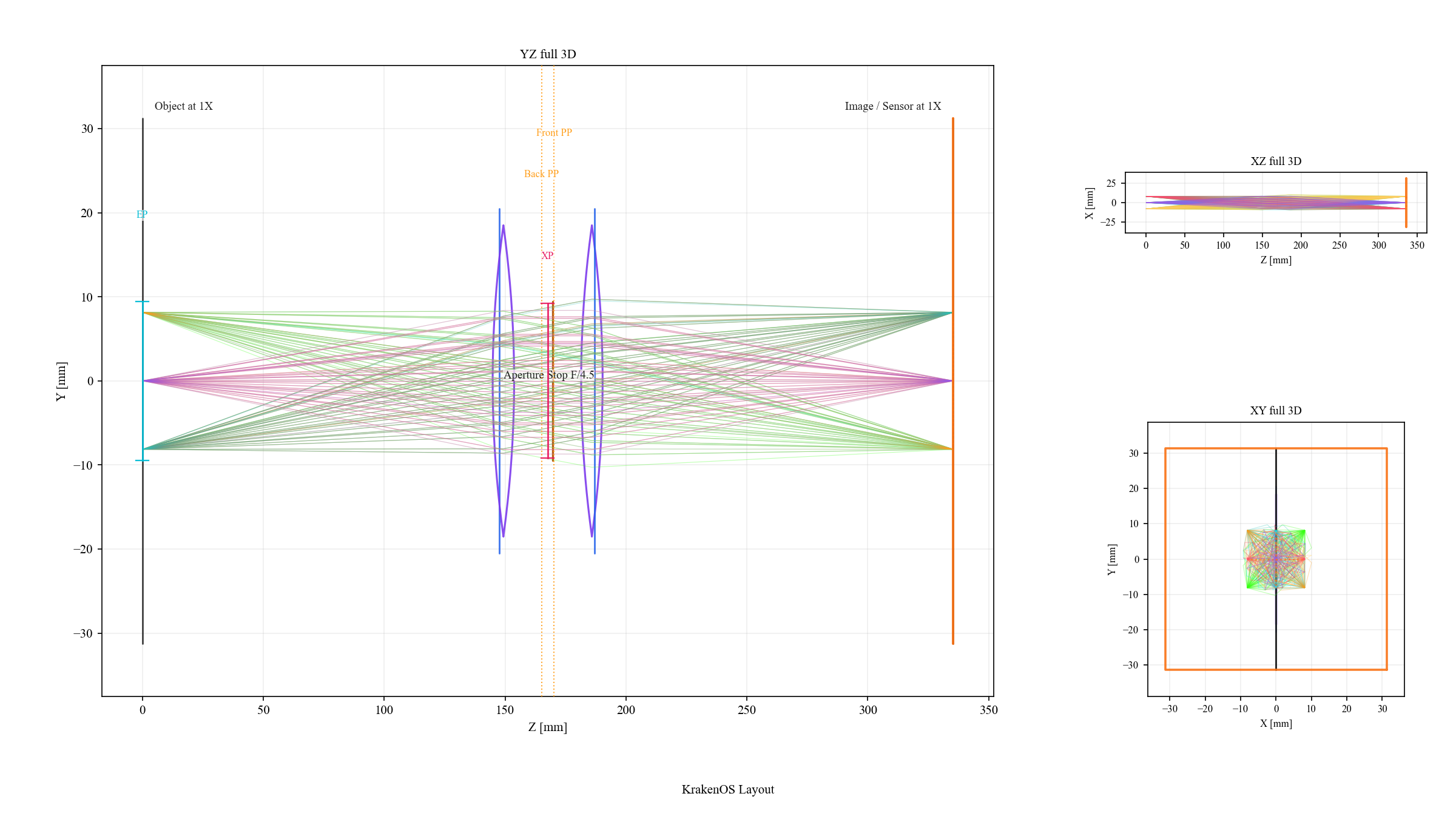
The surrogate uses optical vertex datums, two blackbox thin-lens groups, an F/4.5 stop, and the 1x image plane. It is meant for layout and camera placement studies, not manufacturing-level lens analysis.
Known Limits
Internal curvatures, glasses, aspheres, coatings, tolerances, and MTF are not reconstructed from the datasheet.
The two thin-lens groups reproduce first-order cardinal data; they do not reproduce the vendor’s high-resolution aberration correction.
The mechanical V38 mount, lock screws, filter thread, and barrel outline are represented by the STEP overlay rather than by the sequential surrogate rows.
The STEP overlay is for placement and clearance. The ray trace still uses the two-thin-group blackbox unless the STEP is promoted/rebuilt as native optical surfaces with explicit glass assignments.
Validation
The validation script checks that the layout is discoverable in the Machine
Vision menu and that the two-thin-group paraxial matrix reproduces the published
effective focal length, front focal distance, and back focal distance. It also
loads the vendor STEP and checks that S001/F1030 and S001/F1032 remain
the matched first and last glass surfaces:
python -m KrakenOS.UI.validate_machine_vision_pyrite_85_surrogate