Reference Axis and Mirror Steering
The first alignment task is to establish a line in space independently of the optics that will later be installed. Two separated irises constrain both the beam position and direction; two steering mirrors then transfer a source beam onto that reference line without moving the source body.
Method 1: define the axis with two irises
Place irises \(A_1\) and \(A_2\) at the required beam height and separate them by \(L\). With transverse beam coordinates \(x_1\) and \(x_2\) at the two planes, the small angular error is
This is why two irises are necessary: one iris constrains position but leaves angle undetermined. Separate the irises only after setting both centers to the same height beside a common mechanical datum.
Worked example. Let \(L=0.500\ \mathrm{m}\). The beam is centered at \(A_1\) but is \(0.50\ \mathrm{mm}\) high at \(A_2\):
If left uncorrected, that error becomes 5 mm after another 5 m. Close \(A_1\), correct the source or upstream steering so the beam remains on \(A_1\), then remove the \(A_2\) error. Repeat in horizontal and vertical axes with successively smaller apertures.
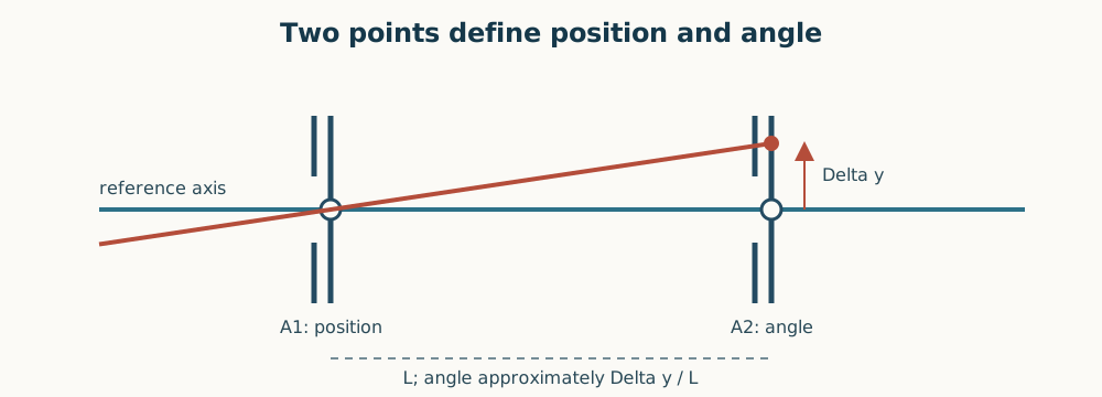
Figure 1. One aperture fixes a point; two apertures fix a line. The measured displacement at \(A_2\) divided by the separation gives the paraxial angular error.
Acceptance check. Translate a viewing card just after each iris without touching the steering controls. The spot must remain centered at both planes when each aperture is reopened to its working diameter. Record the residual \(|x_2-x_1|/L\) and \(|y_2-y_1|/L\), not merely “beam passes.”
Method 2: walk a dog-leg onto the axis
A dog leg uses mirrors \(M_1\) and \(M_2\). The first mirror changes where the beam reaches the second mirror; the second predominantly changes the outgoing angle. For a ray
the desired ray through two reference coordinates is
The mirror response has a factor of two:
Worked example. After centering \(A_1\), the spot is 2.0 mm right at \(A_2\), 0.50 m downstream. The outgoing ray error is 4.0 mrad, so the ideal small correction at \(M_2\) is 2.0 mrad. That correction usually disturbs \(A_1\); use \(M_1\) to restore the near-plane position, then \(M_2\) to halve the far-plane error. Alternate until both errors fall inside tolerance.
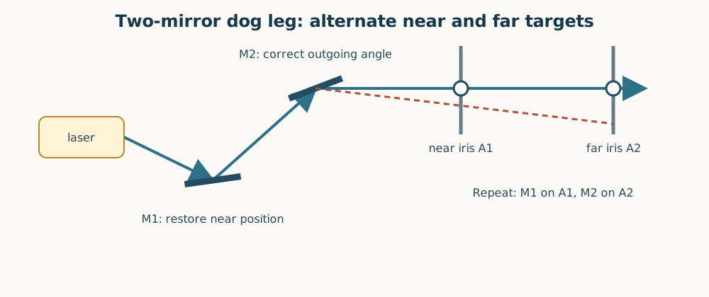
Figure 2. Use \(M_1\) mainly to restore the near target and \(M_2\) mainly to correct the far target. Repetition decouples position and angle.
Do not chase both targets with one mirror. Do not translate an already defined iris to meet the beam. When convergence is complete, lock mounts gently and repeat the measurement because locking torque can shift the spot.