NIR Alignment and Retroreflection
Invisible-beam work is safer and faster when geometry is established with a co-propagating visible reference, then verified at the operating wavelength. Retroreflection supplies an especially sensitive round-trip test, but a plane mirror and a corner cube answer different questions.
Method 11: visible-proxy alignment for NIR
Use a fiber-coupled or dichroically combined visible beam to establish centers, clear apertures, and mirror directions. Replace cards and cameras with wavelength-qualified diagnostics before enabling the NIR source. Recheck all active optical elements because refractive power changes with wavelength.
For a thin lens of fixed curvatures,
Worked example. Using illustrative fused-silica indices \(n_{632.8}=1.457\) and \(n_{1550}=1.444\),
A lens focusing the visible beam at 100.0 mm therefore focuses 1550 nm near 102.9 mm, a 2.9 mm longitudinal shift. Actual values must use the lens glass, prescription, temperature, and vendor wavelength data.
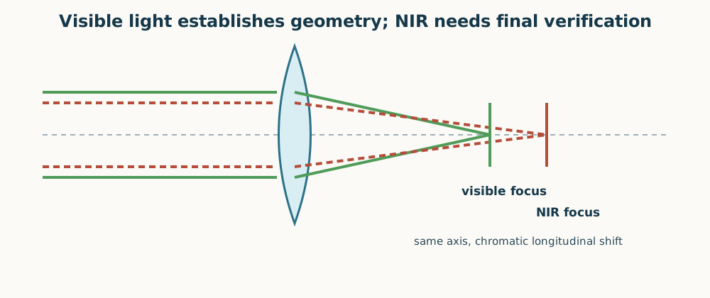
Figure 1. Mirrors and apertures transfer well between wavelengths; lenses, gratings, coatings, fibers, and detectors require wavelength-specific verification.
For a grating, a visible proxy may leave at a different angle because
Treat the visible beam as a mechanical-axis reference, not as proof of the NIR diffracted direction. Use an enclosed IR viewer, fluorescent card, or camera with known response and beam blocks behind every diagnostic.
Method 12: plane-mirror and corner-cube return tests
A plane mirror returns the beam onto itself only when its normal is parallel to the incident beam. At a return target distance \(L\), mirror tilt \(\tau\) produces
A 0.50 mm return displacement measured 1.00 m from the mirror corresponds to \(\tau=0.25\ \mathrm{mrad}\). Use this test to square a surface or close an out-and-back fiber path.
A corner cube returns the chief ray anti-parallel over a range of cube orientations, usually with a lateral offset. It tests whether the receive path accepts a beam parallel to the launch path, but it does not prove that the cube face is normal to the beam. Translate the cube or compensate the known offset before interpreting coupling loss.
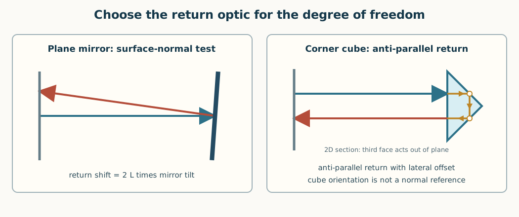
Figure 2. A plane mirror is an angular-normal reference; a corner cube is an anti-parallel return reference. The corner-cube panel is a 2D section: it shows the beam entering the front face and the two in-plane reflections; the third reflecting face acts out of the page. Choose the return optic that measures the required degree of freedom.
For fiber-to-free-space-and-back alignment, place a beamsplitter or circulator to measure returned power, install the corner cube near the intended remote plane, and optimize in this order:
maximize outgoing collimation and clear-aperture margin;
center the corner-cube return on near and far reference planes;
optimize receive-lens \(x,y\), then \(z\), using normalized return power;
perturb each adjustment by a known amount to verify a single local maximum;
lock, remount the remote reflector, and repeat the measurement.
Report round-trip efficiency rather than raw detector power:
This separates alignment from known beamsplitter, window, and reflector losses. The remount test distinguishes a fragile peak from a repeatable alignment.