Chapter 2: Optical Waveguide Modes
Source: Hunsperger, sixth edition (2009), Chapter 2, Problems 2.1–2.11, printed pages 30–31. Use the conventions in Notation, Models, and Checks.
Problem 2.1 — Index interval for one guided order
Model. Use the requested strongly asymmetric approximation with \(n_2=3.4\), \(t=3\,\mu{\rm m}\), and \(\lambda_0=1.10\,\mu{\rm m}\).
Working. The zeroth order must be above cutoff and the first order below cutoff. Equation (3) gives
Answer. \(0.00123570<\Delta n<0.0111213\). The strict upper bound supplies margin below the next-order cutoff.
Check. The cutoff ratio is 9 and both contrasts are small compared with 3.4. This is a spatial-order condition, not proof of one polarization.
Problem 2.2 — Change the wavelength to 1.06 micrometres
Working. Keep the geometry of 2.1 and substitute \(\lambda_0=1.06\,\mu{\rm m}\):
Answer. \(0.00114747<\Delta n<0.0103272\).
Check. Multiplying both endpoints of 2.1 by \((1.06/1.10)^2=0.92860\) recovers this interval. Shorter wavelength requires less contrast at a fixed mode cutoff.
Problem 2.3 — Double the guiding-layer thickness
Working. For \(t=6\,\mu{\rm m}\), divide both earlier cutoff contrasts by four because \(\Delta n_c\propto t^{-2}\).
Vacuum wavelength |
Lower bound |
Upper bound |
|---|---|---|
\(1.10\,\mu{\rm m}\) |
0.000308926 |
0.00278033 |
\(1.06\,\mu{\rm m}\) |
0.000286867 |
0.00258180 |
Answer. Choose a contrast strictly between the appropriate bounds.
Check. This leaves \(t\sqrt{\Delta n}/\lambda_0\) unchanged. Doubling thickness without reducing contrast would permit more orders.
Problem 2.4 — Bounce angle at substrate cutoff
Working. The larger cladding index is \(n_3=1.6\). At cutoff \(\beta=k_0n_3\). Measure the book’s bounce angle from the guide plane:
Answer. \(36.87^\circ\), the maximum bounce angle compatible with substrate total internal reflection; bound modes have smaller angles.
Check. The complementary incidence angle is \(53.1301^\circ=\sin^{-1}(1.6/2)\). It is measured from the normal.
Problem 2.5 — The three lowest symmetric-slab fields
Working. Reflection symmetry makes the fundamental TE field even, with no internal zero. The next field is odd and has one zero at the midplane. The third is even with two internal zeros. Every field decays exponentially in the claddings.
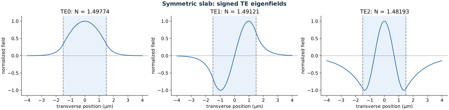
Signed fields. Dashed lines mark core boundaries.
Answer. TE0 has one lobe, TE1 two opposite-sign lobes, and TE2 three alternating-sign lobes.
Check. Interior node count equals order. Squared intensity removes the signs and is not a substitute for the requested field.
Problem 2.6 — Count reflections at one interface
Data. The source diagram supplies \(t=3\,\mu{\rm m}\). \(\beta/(k_0n_2)=0.8\) gives \(\tan\theta=0.6/0.8=0.75\).
Working. One crossing advances the ray by \(t/\tan\theta\) along the guide. Consecutive reflections at the same interface are separated by a round trip:
Answer. Approximately 1250 cover-interface reflections per centimetre; the precise endpoint count depends on initial ray position.
Check. Counting both interfaces would give 2500. The question names only one interface.
Problem 2.7 — Reflection phase at critical incidence
Working. For TE reflection into cladding \(n_j\), set \(\gamma_j=k_0\sqrt{N^2-n_j^2}\). Then
At that interface’s critical angle, \(N\to n_j^+\) and \(\gamma_j\to0\), so the reflection phase tends to zero.
Answer. Both \(\arg r_j\) and the book’s positive half-phase \(\varphi_{2j}\) tend to zero.
Check. At asymmetric-guide cutoff, only the higher-index cladding reaches critical incidence. The other boundary can retain a phase. The lateral Goos–Hänchen displacement is a phase derivative and need not approach zero.
Problem 2.8 — Reflection phases at both boundaries
Working. With \(N=1.85\), \(n_2=2\), \(n_1=1\), and \(n_3=1.7\), cancel the common vacuum wavevector:
Thus \(\varphi_{21}=\tan^{-1}(q/h)=1.11659\) rad and \(\varphi_{23}=\tan^{-1}(p/h)=0.765122\) rad.
Answer. Half-phases: 1.11659 and 0.765122 rad. Full reflection phases for the stated time convention: \(-2.23318\) and \(-1.53024\) rad.
Check. Both decay constants are real because \(N>1.7\). A displacement in metres would also require the wavelength; these dimensionless phases do not.
Problem 2.9 — Wavevector triangle and increasing mode order
Working. Resolve the core wavevector into axial and transverse parts:
At fixed frequency and composition, the hypotenuse is fixed. More transverse oscillations in higher orders require larger \(h\), smaller \(\beta\), and a larger bounce angle.
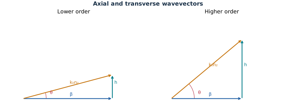
Bounce angle is measured from the axial direction.
Answer. Draw right triangles with a common hypotenuse and progressively taller transverse sides and shorter axial sides.
Check. The last guided order still satisfies \(\beta>k_0n_3\). Below that bound the substrate supports radiation.
Problem 2.10 — Count modes with a quartz overlayer
Data audit. This exercise prints \(n_3=1.05\) for quartz, whereas the similar Problem 4.6 uses 1.5. Keep the printed value here.
Working. Substitute \(n_2=2.09\), \(t=2\,\mu{\rm m}\), and \(\lambda_0=0.6328\,\mu{\rm m}\) into the exact TE cutoff. Part (a) has air cover; part (b) has a thick overlayer with \(n_1=n_3=1.05\). Count orders with \(t>t_{c,m}\).
Answer. Both cases support 12 TE modes, \(m=0,\ldots,11\). The overlayer changes effective indices without changing this integer count. Each also supports 12 TM modes, giving 24 bound vector modes if both polarizations are counted. If 1.5 was intended, the air-covered guide supports 9 TE modes and the symmetric guide supports 10.
Check. In the symmetric case, count nonnegative integers below \(2t\sqrt{2.09^2-1.05^2}/0.6328\simeq11.42\). The conditional 1.5-index totals are 18 and 20 vector modes, respectively.
Problem 2.11 — Fundamental cutoff and doubled thickness
Working. For \(n_2=3.5\), \(n_3=3.38\), \(n_1=1\), and \(\lambda_0=0.88\,\mu{\rm m}\), the exact cutoff gives
The next cutoff is \(t_{c,1}=t_{c,0}+0.88/[2\sqrt{3.5^2-3.38^2}]\). Doubling the fundamental limiting thickness stays below this next cutoff.
Answer. (a) A bound TE0 requires thickness just above 0.19984 micrometres. (b) A thickness of 0.39968 micrometres supports one TE mode.
Check. The numerical dispersion root at the doubled thickness is \(N=3.42701\), between the substrate and core indices.