Chapter 10: Acousto-Optic Modulators
Source: Hunsperger, sixth edition (2009), Problems 10.1–10.10, printed pages 217–219. Optical wavelength inside the guide is \(\lambda_g=2\pi/\beta\), not the vacuum wavelength.
Problem 10.1 — Why optical confinement reduces acoustic drive
Working. The photoelastic relation gives \(\delta n\propto\sqrt{M_2P_a/A_a}\). To obtain a fixed phase or coupling strength over a fixed interaction length, a similar index perturbation is required. Reducing the acoustic cross section \(A_a\) while preserving optical overlap reduces necessary total power. Guiding also keeps light overlapped with the acoustic perturbation over a long interaction distance.
Answer. Concentrate acoustic energy where the optical mode resides, rather than driving an unnecessarily large bulk volume.
Check. Compare equal interaction lengths, efficiencies, and overlap. Confinement does not eliminate acoustic attenuation or electrical transducer conversion loss.
Problem 10.2 — Acoustic index modulation in quartz
Working. Use the book’s fused-quartz value \(M_2=1.51\times10^{-18}\,{\rm s^3/g} =1.51\times10^{-15}\,{\rm s^3/kg}\). The driven cross section is \(A=(3\times10^{-6})(100\times10^{-6})=3\times10^{-10}\,{\rm m^2}\).
Answer. About 0.00159 under the book’s uniform-overlap convention.
Check. The cgs-to-SI mass conversion is essential. The value depends on the selected material orientation and photoelastic coefficient.
Problem 10.3 — Bragg angle and diffracted-beam width
Working. The supplied propagation constant gives \(\lambda_g=2\pi/(20.85\,\mu{\rm m}^{-1})=0.301352\,\mu{\rm m}\). With acoustic period 2.5 micrometres,
This angle is from the acoustic wavefront, so the incident beam makes 86.5447 degrees with acoustic propagation; its diffracted counterpart makes 93.4553 degrees on the opposite side.
For a uniform 4 mm optical aperture, the exact sinc-squared far-field full width at half maximum is \(0.885893\lambda_g/b=0.003824^\circ\). The book’s approximate Eq. (10.15), \(\lambda_g/b\), gives 0.004317 degrees.
Answer. Incidence 86.545 degrees from acoustic propagation; diffraction at the complementary Bragg direction, with the above full half-power width.
Check. The 2 mm interaction length instead controls angular/spectral acceptance; it is not the optical-aperture width. Use the measured modal propagation constant, rather than substituting the bulk index 2.295.
Problem 10.4 — Refraction before and after Bragg diffraction
Working. Assume the butt faces are perpendicular to the nominal optical axis and acoustic propagation is transverse to it. The incident GaAs ray is tilted 3 degrees from that axis. Tangential momentum at the GaAs/LiNbO3 face gives \(n_{\rm LN}\sin\theta_B=3.59\sin3^\circ\). Thus
Answer. About 3.06 micrometres acoustic wavelength; the diffracted beam exits about 10.83 degrees from the output-face normal, on the deflected side.
Check. Treating the initial 3 degrees as an internal LiNbO3 angle ignores the stated GaAs input medium. A different face orientation would require a different Snell construction.
Problem 10.5 — Transit-time bandwidth
Working. Acoustic transit across 50 micrometres takes
The inverse transit time is only 5 MHz; detailed transfer functions change the numerical coefficient, not the two-order-of-magnitude mismatch.
Answer. This geometry cannot reproduce a 100 MHz modulation envelope across the full optical interaction aperture.
Check. Acoustic carrier frequency and modulation bandwidth are different. A fast carrier alone does not overcome aperture transit delay.
Problem 10.6 — Interdigital pitch and optical deflection
Working. \(\Lambda=v_a/f_a=2800/10^8=28\,\mu{\rm m}\). In a conventional single-electrode alternating-polarity IDT, adjacent finger centres are separated by \(\Lambda/2=14\,\mu{\rm m}\); equal-polarity fingers repeat every 28 micrometres. For a 50 percent metal fill, finger width and edge gap are 7 micrometres.
Answer. 14 micrometre adjacent centre pitch and about 0.589 degrees internal optical deflection.
Check. “Finger spacing” can mean edge gap or centre pitch; the dimensions above distinguish them explicitly.
Problem 10.7 — One-degree Bragg operation
Working. The Bragg angle is half the optical deflection:
Answer. An alternating IDT has adjacent centre pitch 5.6654 micrometres and same-polarity repeat 11.3308 micrometres.
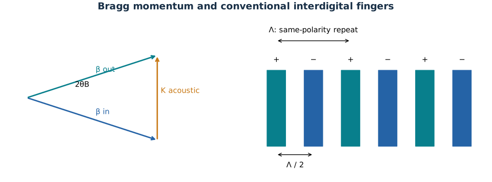
The grating vector supplies transverse momentum; the two optical directions are separated by twice the Bragg angle.
Check. If 1 degree meant total deflection instead of Bragg angle, the acoustic period would be approximately twice as large.
Problem 10.8 — Analyzer at 500 megahertz
Working. With \(n=2\), \(\lambda_g=0.3164\,\mu{\rm m}\). At 500 MHz, acoustic period is 6 micrometres. The deflection is \(\Delta\theta\simeq\lambda_g/\Lambda=0.0527333\) rad. Use the question’s envelope-width definition of resolution:
Answer. About 3.021 degrees deflection and 7.59 envelope-width resolution elements in the book’s approximation.
Check. This is not \(f_ab/v_a\); that expression incorrectly uses carrier frequency in place of the accepted acoustic bandwidth. The full 50–500 MHz operating range is not necessarily flat-efficiency bandwidth for one fixed Bragg alignment.
Problem 10.9 — Analyzer at 100 megahertz
Working. Acoustic wavelength increases to \(\Lambda=3000/(100\times10^6)=30\,\mu{\rm m}\). Keep optical beam width and interaction length unchanged:
Answer. About 0.6043 degrees deflection and 37.93 envelope-width resolution elements.
Check. Relative to 500 MHz, deflection is divided by five, whereas the approximate Bragg acceptance envelope grows by five.
Problem 10.10 — Measured modulation depth and inconsistent units
Working. The prompt labels the initial quantity as intensity (200 mW/cm2) but the final quantity as power (175 mW). These cannot be divided without an illuminated area. If the intended final intensity is 175 mW/cm2, the removed zeroth-order fraction is
Answer. Under that explicit same-intensity-unit interpretation, 12.5 percent of the original beam is modulated out of the zeroth order. If “modulation depth” means \((I_{\max}-I_{\min})/(I_{\max}+I_{\min})\), it is \(25/375=6.667\) percent.
Check. With the mixed units taken literally, no unique numerical depth follows. The quoted acoustic power does not supply the missing illuminated area.