Chapter 3: Theory of Optical Waveguides
Source: Hunsperger, sixth edition (2009), Problems 3.1–3.10, printed pages 48–49. The full core thickness is used throughout.
Problem 3.1 — Oscillatory and evanescent constants
Working. Substitute \(E_y(x,z,t)=F(x)e^{i\omega t-i\beta z}\) into the source-free Helmholtz equation in region \(j\):
In the core, \(\beta<k_0n_2\), so the coefficient is positive and the solution is sinusoidal with \(h^2=k_0^2n_2^2-\beta^2\). In the claddings, \(\beta>k_0n_j\), giving decaying exponentials.
Answer. \(h=\sqrt{k_0^2n_2^2-\beta^2}\), \(q=\sqrt{\beta^2-k_0^2n_1^2}\), and \(p=\sqrt{\beta^2-k_0^2n_3^2}\).
Check. All have units of inverse length. Select the exterior exponential signs so the field decreases away from the core on both sides.
Problem 3.2 — Derive the asymmetric weak-step condition
Working. At substrate cutoff, \(p=0\). For a strongly asymmetric guide \(q/h\gg1\), so the remaining reflection half-phase tends to \(\pi/2\). The resonance condition becomes
Squaring and using \(k_0=2\pi/\lambda_0\) gives
Answer. Propagation requires a contrast greater than this limiting value within the stated approximation.
Check. This is not the exact cutoff for arbitrary cladding indices. It assumes both strong asymmetry and \(\Delta n\ll n_2\).
Problem 3.3 — Rectangular electric fields
Working. A separable interior approximation on \(0<x<a,\ 0<y<b\) is
Thus \(E^y_{12}\) has one lobe across \(x\) and two opposite-sign lobes across \(y\). \(E^y_{22}\) has four lobes in a checkerboard of alternating signs. Continue the fields as evanescent tails outside the dielectric core rather than literal zero walls.
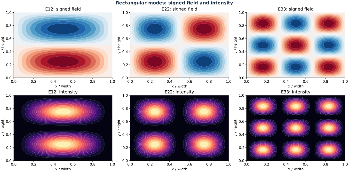
Separable schematic fields (top) and squared magnitudes (bottom).
Answer. The nodal-line counts are \(m-1\) and \(n-1\) along the two transverse coordinates.
Check. This sketches the dominant component of a dielectric hybrid mode, not an exact metallic-waveguide boundary solution.
Problem 3.4 — Rectangular optical power distributions
Working. In the same separable approximation, power density is proportional to \(|E^y_{mn}|^2\). Consequently \(E^y_{33}\) has a three-by-three array of nine positive intensity lobes, with two dark nodal lines in each direction. \(E^y_{22}\) has a two-by-two array of four lobes.
Answer. Use the lower row of the preceding figure: negative field lobes become positive intensity lobes, while field nodes stay dark.
Check. Intensity cannot be negative. For precise vector-mode power use \(\frac12\operatorname{Re}(\mathbf E\times\mathbf H^*)\); the dominant-field sketch is sufficient to identify the requested lobes.
Problem 3.5 — Symmetric slab counts and fundamental limit
Working. For a symmetric slab, cutoff is \(V=m\pi\), where \(V=(2\pi t/\lambda_0)\sqrt{n_2^2-n_c^2}\). Use \(t=3\,\mu{\rm m}\), \(n_2=1.5\), and \(\lambda_0=0.6328\,\mu{\rm m}\). Count integers \(m\ge0\) strictly smaller than \(V/\pi\).
Answer. (a) Air claddings give 11 TE modes. (b) Claddings of index 1.48 give 3 TE modes. (c) The ideal symmetric dielectric slab supports TE0 for every positive thickness; its limiting cutoff thickness is zero.
Check. Zero itself is not a finite guide. As thickness approaches zero, confinement vanishes and the field extends arbitrarily far into the cladding.
Problem 3.6 — Single-mode thickness and bounce angle
Data. Take the uncovered surface as air: \(n_1=1,\ n_2=1.62,\ n_3=1.346,\ \lambda_0=0.6328\,\mu{\rm m}\).
Working. Applying the exact TE cutoff to orders zero and one gives
For the supplied \(\beta=1.53\times10^5\,{\rm cm}^{-1}\), convert wavelength to centimetres before forming \(\cos\theta=\beta\lambda_0/(2\pi n_2)\).
Answer. (a) One TE order occurs for \(0.0877103<t<0.438685\,\mu{\rm m}\). (b) \(\theta=17.977^\circ\) from the guide plane, or 72.023 degrees from its normal.
Check. If “one mode” means only one vector polarization as well, TM0 begins at \(0.134793\,\mu{\rm m}\); the TE-only interval ends there. A sketch must label which angle is being drawn.
Problem 3.7 — Exact asymmetric TE count
Working. Insert \(n_2=1.65,\ n_3=1.52,\ n_1=1\) and \(\lambda_0=0.63\,\mu{\rm m}\) into (2). The cutoff sequence is an arithmetic progression starting at \(t_{c,0}=0.165518\,\mu{\rm m}\) with spacing \(\lambda_0/(2\sqrt{n_2^2-n_3^2})\). At \(t=1.18\,\mu{\rm m}\) the first three, and only those, are exceeded.
Answer. Three TE modes: TE0, TE1, and TE2.
Check. The dispersion roots are \(N=1.63494,\ 1.59010,\ 1.52251\). The highest order is only weakly above the substrate index 1.52.
Problem 3.8 — Why symmetry helps retain the fundamental
Working. At symmetric cutoff both exterior decay constants vanish, so the TE0 phase condition is \(ht=0\). The mode therefore has no positive minimum thickness. In an asymmetric guide, the higher-index substrate reaches cutoff while the cover still supplies a reflection phase. A positive thickness is needed to balance that phase.
Answer. Symmetry removes the positive TE0 cutoff and avoids loss of the fundamental through cover/substrate index imbalance.
Check. This does not mean every symmetric guide is single-mode. Thickness must still stay below TE1 cutoff. At fixed contrast, compare the actual two cutoff boundaries rather than assuming all fabrication tolerances necessarily improve.
Problem 3.9 — Optical stripline and ray confinement
Working. A loading strip on an otherwise planar dielectric guide changes the local vertical boundary conditions. The region beneath it has a larger local effective index than the uncovered film. The vertical slab first confines light normal to the wafer; the effective-index step then provides lateral confinement.
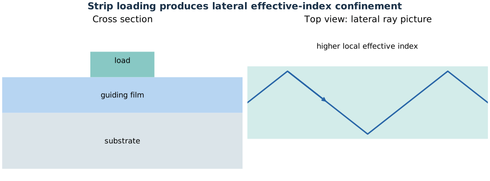
The loading strip changes modal effective index; it need not exceed the core’s material index.
Answer. Draw vertical reflections at the slab boundaries and a lateral zigzag within the loaded strip region.
Check. Lateral ray confinement depends on local effective indices, not merely on the bulk indices of strip and substrate.
Problem 3.10 — Phase velocity beneath a loading strip
Working. At fixed optical frequency, \(\beta=k_0N\) and \(v_{\rm ph,z}=\omega/\beta=c/N\). Loading raises the local effective index, so it increases \(\beta\) and lowers axial phase velocity.
Answer. The phase velocity is smaller beneath the strip.
Check. The core’s bulk index need not change. The speed comparison is for the guided mode’s axial phase, not a claim about a group velocity without dispersion data.